EN
8
– English
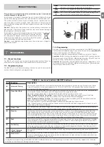
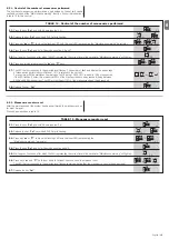
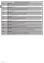
7.5 - Level two programming (adjustable parameters)
The adjustable parameters are factory set as shown in the table 7 with: “
”
However, they can be changed at any time as shown in Table 8. Follow
the procedure carefully, as there is a maximum time of 10 seconds between
pressing one key and another. If a longer period of time lapses, the procedure
will finish automatically and memorize the modifications made up to that stage.
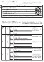
TABLE 6
-
Changing ON-OFF functions
01.
Press the key “
Set
” and hold it down (approx. 3 s);
02.
Release the “
Set
” key when “
L1
” LED starts flashing;
03.
Press keys “
s
” or “
t
” to move the flashing LED onto the LED representing the function which is to be changed;
04.
Press the “
Set
” key to change the state of the function:
(short flashing = OFF; long flashing = ON);
05.
Wait 10 seconds before leaving the programme to allow the maximum time to lapse.
Note
– Points 3 and 4 can be repeated during the same programming phases in order to set other functions to ON or OFF.
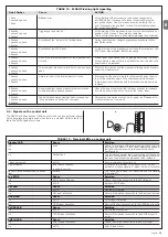
7.4 - Level one programming (ON-OFF functions)
Level 1 functions are all factory set to “OFF”. However, they can be changed
at any time as shown in Table 6. Follow the procedure carefully, as there is a
maximum time of 10 seconds between pressing one key and another. If a lon-
ger period of time lapses, the procedure will finish automatically and memorize
the modifications made up to that stage.
L2
L1
L2
L3
L4
L5
L6
L7
L8
Open – stop – close – stop
Open – stop – close – open
Open – close – open – close
Condominium operation
Condominium operation 2 (more than 2” causes stop)
Step-by-Step 2 (less than 2” causes partial opening)
Man present
“Semiautomatic” opening, “Man present “ closing
Manages the sequence of controls
associated to the Step-by-Step input
(Sbs) or to the 1st radio command.
Step-by-
step
L3
L1
L2
L3
L4
L5
L6
L7
L8
Very slow
Slow
Medium
Fast
Very fast
Extremely Fast
Opens “Fast”; closes “slow”
Opens “Extremely Fast” Closes “Fast”
Adjusts the speed of the motor during
normal travel.
Motor
speed
L1
L1
L2
L3
L4
L5
L6
L7
L8
5 seconds
15 seconds
30 seconds
45 seconds
60 seconds
80 seconds
120 seconds
180 seconds
Adjusts the pause time, namely the
time which lapses before automatic
closure. This will only have an effect
if automatic closing is active.
Pause
Time
L4
L1
L2
L3
L4
L5
L6
L7
L8
Open Gate Indicator Function
On if leaf closed
On if leaf open
Active with 2
nd
radio output
Active with 3
rd
radio output
Active with 4
th
radio output
Maintenance indicator
Electric lock
Adjusts the function associated with
the OGI output (whatever the asso-
ciated function may be, the output
supplies a voltage of 24V –30 +50%
with a maximum power of 4W when
active).
Open Gate
Indicator
Output
L5
L1
L2
L3
L4
L5
L6
L7
L8
Super light gate
“Very light” gate
“Light” gate
“Average” gate
“Average-heavy” gate
“Heavy” gate
“Very heavy” gate
“Super heavy” gate
Adjusts the system which controls
the motor force in order to adapt it
to the weight of the gate. The force
control system also measures the
ambient temperature, automatically
increasing the force in the event of
particularly low temperatures.
Motor
force
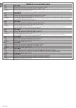
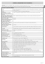
TABLE 7 - Level two functions (adjustable parameters)
Imput
Parameter
LED Value
Description
LED
(level)
Stop/Se
t
Stop/Se
t
Stop/Se
t
L1
Ope
n
Clos
e
o
3 s
10 s
Summary of Contents for Naked Sliding NKSL400
Page 2: ......
Page 43: ...I 405 mm 131 mm 135 mm 1 3 4 5 b d c c h l b f m g i n e a E C F D C F A B 2...
Page 44: ...II b a b a c 5 mm 6 7 10 11 8 9...
Page 46: ...IV 14 15...
Page 48: ...VI 19 20 a b c d e...
Page 49: ...VII 21 22...
Page 50: ......
Page 51: ......


