EN
14
– English
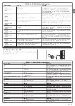
TABLE 16 - Troubleshooting
Symptoms
Recommended check
The radio transmitter does not control the gate
and the LED on the transmitter does not light
up
The radio transmitter does not control the gate but
the LED on the transmitter lights up
No manoeuvre starts and the “BlueBUS” LED
does not flash
No manoeuvre starts and the flashing light is off
No manoeuvre starts and the flashing light flashes
a few times
The manoeuvre starts but it is immediately fol-
lowed by a reverse run
The manoeuvre is carried out but the flashing light
does not work
The manoeuvre is carried out but the Open Gate
Indicator does not work
Check to see if the transmitter batteries are exhausted, if necessary replace them
Check to see if the transmitter has been memorised correctly in the radio receiver
Check that NAKED is powered by a 230V mains supply.
Check to see if the fuses F1 and F2 are blown; if necessary, identify the reason for the failure and
then replace the fuses with others having the same current rating and characteristics.
Make sure that the command is actually received. If the command reaches the STEP-BY-STEP
input, the corresponding “STEP-BY-STEP” LED must light up; if you are using the radio transmit-
ter, the “BlueBus” LED must make two quick flashes.
Count the flashes and check the corresponding value in table 18
The selected force could be too low for this type of gate. Check to see whether there are any
obstacles; if necessary increase the force
Make sure that there is voltage on the flashing light’s FLASH terminal during the manoeuvre (being
intermittent, the voltage value is not important: approximately 10-30Vdc); if there is voltage, the
problem is due to the lamp; in this case replace the lamp with one having the same characteristi-
cs; if there is no voltage, there may have been an overload on the FLASH output. Check that the
cable has not short-circuited.
Check the type of function programmed for the OGI output (Table 7)
When the light should be on, check there is voltage on the OGI terminal (approximately 24Vdc). If
there is voltage, then the problem will have been caused by the light, which will have to be repla-
ced with one with the same characteristics. If there is no voltage, there may have been an overlo-
ad on the OGI output. Check that the cable has not short-circuited.
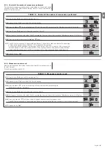
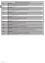
TABLE 17
-
Malfunctions archive
01.
Press the key “
Set
” (approx. 3 s);
02.
Release the key “
Set
” key when
L1
LED starts flashing;
03.
Press key “
s
” or “
t
” to move the flashing LED onto the input LED L8 representing
the “malfunctions list” parameter;
04.
Press the key “
Set
”, and hold it down during step 5 and 6;
05.
Wait for about 3s after which the LEDs corresponding to the manoeuvres in which the defect occurred will light. The L1 LED
indicates the result of the last manoeuvre and L8 indicates the result of the 8th manoeuvre. If the LED is on, this means that
a defect occurred during that manoeuvre; if the LED is off, this means that no defect occurred during that manoeuvre;
06.
Press keys “
s
” and “
t
” to select the required manoeuvre: The corresponding LED flashes the same number of times
as those made by the flashing light after a defect (see table 18);
07.
Release the key “
Set
”.
9.2 - Malfunctions archive
NAKED allows the possible malfunctions that have occurred in the last 8 mano-
euvres to be viewed; for example, the interruption of a manoeuvre due to a
photocell or sensitive edge cutting in. To verify the malfunctions list, proceed
as in table 17.
9.3 - Flashing light signalling
During the manoeuvre the flashing light FLASH flashes once every second. When
something is wrong the flashes are more frequent; the light flashes twice with a
second’s pause between flashes.
WHAT TO DO IF…
(troubleshooting guide)
9
9.1 - Troubleshooting
The table 16 contains instructions to help you solve malfunctions or errors that
may occur during the installation stage or in case of failure.
F2
F1
Stop/Se
t
L1
Ope
n
Clos
e
o
Ope
n
Clos
e
e
Stop/Se
t
Stop/Se
t
Stop/Se
t
3 s
3 s
L8
Summary of Contents for Naked Sliding NKSL400
Page 2: ......
Page 43: ...I 405 mm 131 mm 135 mm 1 3 4 5 b d c c h l b f m g i n e a E C F D C F A B 2...
Page 44: ...II b a b a c 5 mm 6 7 10 11 8 9...
Page 46: ...IV 14 15...
Page 48: ...VI 19 20 a b c d e...
Page 49: ...VII 21 22...
Page 50: ......
Page 51: ......

