background image

IT

Italiano – 

15

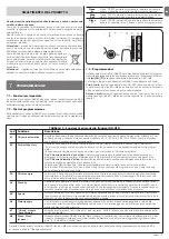
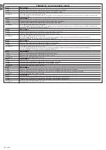
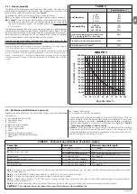
TABELLA 18 - Segnalazioni sul lampeggiante FLASH

Lampeggi veloci 

Causa 

AZIONE

1 lampeggio

pausa di 1 secondo

1 lampeggio

Errore sul sistema Bluebus

All’inizio della manovra, la verifica dei dispositivi collegati a 

BLUEBUS non corrisponde a quelli memorizzati durante la 

fase di apprendimento. E’ possibile vi siano dispositivi guasti, 

verificare e sostituire; se sono state fatte delle modifiche occor-

re rifare l’apprendimento 

2 lampeggi

pausa di 1 secondo

2 lampeggi

Intervento di una fotocellula

All’inizio della manovra una o più fotocellule non danno il consen-

so al movimento; verificare se sono presenti ostacoli. Durante il 

movimento è normale se effettivamente è presente un ostacolo.

3 lampeggi

pausa di 1 secondo

3 lampeggi

Intervento del limitatore della “Forza Motore”

Durante il movimento il cancello ha incontrato un maggiore 

attrito;

verificare la causa

6 lampeggi

pausa di 1 secondo

6 lampeggi

Superato il limite massimo di manovre per ora

Attendere alcuni minuti in modo da far ritornare il limitatore di 

ma novre sotto il limite massimo.

7 lampeggi

pausa di 1 secondo

7 lampeggi

Errore nei circuiti elettrici interni

Scollegare tutti i circuiti di alimentazione per qualche secondo poi 

riprovare a dare un comando; se lo stato rimane potrebbe esser-

ci un guasto grave ed occorre sostituire la scheda elettronica

8 lampeggi

pausa di 1 secondo

8 lampeggi

È già presente un comando che non consente di 

eseguire altri comandi.

Verificare la natura del comando sempre presente; ad esempio 

potrebbe essere il comando da un orologio sull’ingresso di 

“apre”.

4 lampeggi

pausa di 1 secondo

4 lampeggi

Intervento dell’ingresso di STOP

All’inizio della manovra o durante il movimento c’è stato un 

intervento dell’ingresso di STOP; verificare la causa.

5 lampeggi

pausa di 1 secondo

5 lampeggi

Errore nei parametri interni della centrale di coman-

do

Attendere almeno 30 secondi e poi riprovare a da re un coman-

do; se lo stato rimane, potrebbe esserci un guasto grave ed 

occorre sostituire la scheda elettronica.

9 lampeggi

pausa di 1 secondo

9 lampeggi

L’automazione è stata bloccata da un comando 

“Blocca l’automazione”

Sbloccare l’automazione inviando il comando “Sblocca auto-

mazione”

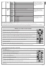
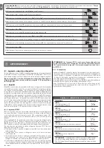
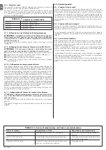
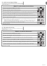
9.4 - Segnalazioni sulla centrale

Nella centrale di NAKED ci sono una serie di LED ognuno dei quali può dare 

delle segnalazioni particolari, sia nel funzionamento normale che in caso di ano-

malia. Vedere tabella 19, tabella 20 e figura a lato.

TABELLA 19 - Led dei morsetti presenti sulla centrale di comando

Led Bluebus 

Causa 

Soluzione

Spento 

Anomalia 

Verificare se c’è alimentazione; verificare che i fusibili  


non siano intervenuti; nel caso, verificare la causa del  


guasto e poi sostituirli con altri del lo stesso valore.

Acceso 

Anomalia grave 

C’è una anomalia grave; provare a spegnere per qualche  


secondo la centrale; se lo stato permane c’è un guasto e  


occorre sostituire la scheda elettronica.

1 lampeggio al secondo 

Tutto OK 

Funzionamento normale della centrale

2 lampeggi veloci 

È avvenuta una variazione dello stato degli ingressi 

È normale quando avviene un cambiamento di uno degli  


ingressi: STOP, OPEN, intervento delle fotocellule o viene 


utilizzato il trasmettitore radio.

Serie di lampeggi separati da una pausa  

Varie 

È la stessa segnalazione che c’è sul lampeggiante  

di 1 secondo 


(vedere Tabella 20)

Led STOP 

Causa 

Soluzione

Spento 

Intervento dell’ingresso di STOP 

Verificare i dispositivi collegati all’ingresso di STOP

Acceso 

Tutto OK 

Ingresso STOP attivo

Led Sbs Causa 

Soluzione

Spento 

Tutto OK 

Ingresso Sbs non attivo

Acceso 

Intervento dell’ingresso di Sbs 

È normale se è effettivamente attivo il dispositivo  


collegato all’ingresso di Sbs

Led OPEN 

Causa 

Soluzione

Spento 

Tutto OK 

Ingresso OPEN non attivo

Acceso 

Intervento dell’ingresso di OPEN 

È normale se è effettivamente attivo il dispositivo  


collegato all’ingresso di OPEN

Led CLOSE 

Causa 

Soluzione

Spento 

Tutto OK 

Ingresso CLOSE non attivo

Acceso 

Intervento dell’ingresso di CLOSE 

È normale se è effettivamente attivo il dispositivo  


collegato all’ingresso di CLOSE

Led AUX_IN Causa 

Soluzione

Spento 

Apertura contatto dell’ingresso AUX_IN 

Verificare i dispositivi collegati all’ingresso AUX_IN

Acceso 

Tutto OK 

Ingresso AUX_IN attivo

er

1.6AT

B

L1
L2

L3
L4
L5

L6
L7

L8

Open

Stop/Se

t

Close

Summary of Contents for Naked Sliding NKSL400

Page 1: ...IT Istruzioni ed avvertenze per l installazione e l uso EN Instructions and warnings for installation and use Recessed sliding gate opener NKSL400 Nice...

Page 2: ......

Page 3: ...uentemente l impianto in particolare controllare i cavi le molle e i supporti per rilevare eventuali sbilanciamenti e segni di usura o danni Non usare se necessaria una riparazione o una regolazione p...

Page 4: ...olonna nell impianto Attenzione Assicurarsi che la colonna sia adeguatamente predisposta nel rispetto delle normative del territorio e che garantisca con il coperchio chiuso un grado di protezione alm...

Page 5: ...ettrici Collegamento Tipo di cavo Lunghezza massima consentita A Linea elettrica di alimentazione cavo 3 x 1 5 mm2 30 m nota 1 B Lampeggiante con antenna N 1 cavo 2x0 5mm2 20m N 1 cavo schermato tipo...

Page 6: ...agliera gi presente eseguire la regolazione dei finecorsa meccanici come descritto nel paragrafo 3 6 Se la cremagliera da installare procedere nel modo seguente a Portare manualmente l anta ad una dis...

Page 7: ...zione a NAKED deve esse re eseguito da personale esperto qualificato in possesso dei requisiti richiesti e nel pieno rispetto di leggi norme e regolamenti Non appena viene fornita tensione a NAKED con...

Page 8: ...ore come indicato nel paragrafo Sblocco e movi mento manuale sul capitolo Istruzioni ed avvertenze destinate all utilizza tore del motoriduttore NAKED 03 Verificare che sia possibile muovere manualmen...

Page 9: ...ona da Master e uno da Slave per maggiori dettagli vedere il para grafo 8 1 5 NAKED in modalit Slave SMALTIMENTO DEL PRODOTTO Questoprodotto parteintegrantedell automazione edunque deveessere smaltito...

Page 10: ...di controllo della forza misura anche la temperatura ambientale aumen tando automaticamente la forza in caso di temperature particolarmen te basse Forza motore TABELLA 7 Funzioni di secondo livell par...

Page 11: ...zione per regolare pi parametri Stop Set Stop Set Stop Set L6 L1 L2 L3 L4 L5 L6 L7 L8 0 5 mt 1 mt 1 5 mt 2 mt 2 5 mt 3 mt 3 4 mt 4 mt Regola la misura dell apertura parziale L apertura parziale si pu...

Page 12: ...afo 8 1 6 Apprendimento altri dispositivi 8 1 2 Ingresso STOP STOP l ingresso che provoca l arresto immediato della manovra seguito da una breve inversione A questo ingresso possono essere collegati d...

Page 13: ...AKED funziona come Slave cio esegue i comandi inviati dal Master di fab brica tutti i NAKED sono Master A Per configurare NAKED come Slave bisogna attivare la funzione di primo livello Modo Slave vede...

Page 14: ...imenti consultare il rispettivo manuale istruzioni ed il manuale del sistema Opera system book 8 1 11 Collegamento del sistema ad energia solare Solemyo ATTENZIONE Quando l automazione alimentata dal...

Page 15: ...mantenere premuto il tasto Set il tasto Set va mantenuto premuto durante tutti i passi 5 6 e 7 05 Attendere circa 3s dopodich si accender il led che rappresenta il livello attuale del parametro Avviso...

Page 16: ...aratteristiche Verificare che il comando venga effettivamente ricevuto Se il comando giunge sull ingresso Sbs il relativo led Sbs deve accendersi se invece viene utilizzato il trasmettitore radio il l...

Page 17: ...ronica 9 lampeggi pausa di 1 secondo 9 lampeggi L automazione stata bloccata da un comando Blocca l automazione Sbloccare l automazione inviando il comando Sblocca auto mazione 9 4 Segnalazioni sulla...

Page 18: ...e paragrafo 5 4 Apprendimento lunghezza dell anta Led 4 Descrizione Spento Durante il funzionamento normale indica Stand By non attivo Acceso Durante il funzionamento normale indica Stand By attivo La...

Page 19: ...dinamico fino a 400N 6Nm corrispondente alla capacit di mantenere in movimento un anta con attrito dinamico fino a 200N 0 18m s 0 34m s 35 cicli ora la centrale limita i cicli al massimo previsto nel...

Page 20: ...rettiva secondo i requisiti previsti per le quasi macchina Allegato II parte 1 sezione B Direttiva 2006 42 CE DEL PARLAMENTO EUROPEO E DEL CONSIGLIO del 17 maggio 2006 relativa alle macchine e che mod...

Page 21: ...o un attivazione sempre prevedibile e sicura comunque prudente vietare ai bambini di giocare in prossi mit dell automazione e per evitare attivazioni involontarie non lasciare i telecomandi alla loro...

Page 22: ...rare quanto prima l automatismo Sostituzione pila del telecomando se il vostro radio comando dopo qualche tempo vi sembra funzionare peg gio oppure non funzionare affatto potrebbe semplicemen te dipen...

Page 23: ...maintenance cleaning always disconnect the product from the mains power supply Check the system periodically in particular all cables springs and supports to detect possible imbalances signs of wear o...

Page 24: ...re there is no danger of the gate derailing Make sure that the mechanical stops are sturdy enough and that there is no risk of the deformation even when the leaf hits the mechanical stop violently Mak...

Page 25: ...ble 2x0 5mm2 note 4 30m note 5 Note 1 power supply cable longer than 30 m may be used provided it has a larger gauge e g 3x2 5mm2 and that a safety grounding system is provided near the automation uni...

Page 26: ...e nut provided being careful to close it on the flat surface of the pin 05 At this point if there is already a rack adjust the mechanical limit switches as described in point 3 6 If the rack is to be...

Page 27: ...he connection of NAKED to the mains must be made by qualified and experienced personnel in possession of the necessary requisites and in full respect of the laws provisions and standards cur rently in...

Page 28: ...d in particular in chapter 1 WARNINGS have been observed in full 02 Release the gearmotor as shown in Release and manual movement paragraph in chapter Instructions and Warnings for users of the NAKED...

Page 29: ...nput activate a partial opening manoeuvre see LED L6 on table 7 By activating this function NAKED becomes Slave in this way it is possible to synchronise the functioning of two motors on opposite leav...

Page 30: ...ion 2 more than 2 causes stop Step by Step 2 less than 2 causes partial opening Man present Semiautomatic opening Man present closing Manages the sequence of controls associated to the Step by Step in...

Page 31: ...the adjustable parameters 01 Press the key Set and hold it down approx 3 s 02 Release the Set key when L1 LED starts flashing 03 Press the key s or t to move the flashing LED onto the input LED repres...

Page 32: ...rse run Devices with output featuring normally open NO contacts and devices with normally closed NC contacts as well as devices with 8 2K constant resistance output like sensitive edges can be connect...

Page 33: ...ses where there is a passage of heavy vehicles and a second photocell is normally placed at 1 m from the ground See the FT210B instructions manual for further information concerning con nection and ad...

Page 34: ...precautions up to 60 with the warnings stated and may be left connected up to the unit during regular operation of the automation mechanism In this case it may be used to send commands directly to the...

Page 35: ...key Set TABLE 15 Manoeuvre counter reset 01 Press the key Set and hold it down approx 3 s 02 Release the key Set key when L1 LED starts flashing 03 Press key s or t to move the flashing LED onto the i...

Page 36: ...hort circuited Check the type of function programmed for the OGI output Table 7 When the light should be on check there is voltage on the OGI terminal approximately 24Vdc If there is voltage then the...

Page 37: ...ersists it means there is a malfunction and the electronic board has to be replaced 9 flashes 1 second s pause 9 flashes The automation mechanism has been stopped by a Stop automation mechanism comman...

Page 38: ...r to Paragraph 5 4 Recognition length of the leaf Led 4 Description Off During normal operation the device indicates Stand by is not active On During normal operation the device indicates Stand by is...

Page 39: ...dinamico fino a 400N 6Nm corrispondente alla capacit di mantenere in movimento un anta con attrito dinamico fino a 200N 0 18m s 0 34m s 35 cycles day the control unit allows up to the maximum describe...

Page 40: ...the requirements envisaged for partly completed machinery Annex II part 1 section B Directive 2006 42 EC of the EUROPEAN PARLIAMENT AND COUNCIL of 17 May 2006 related to machinery and amen ding the D...

Page 41: ...gh levels of safety and security They are equipped with detection devices that prevent movement if people or objects are in the way guaranteeing safe and reliable acti vation However children should n...

Page 42: ...st be repaired as soon as possi ble Replacing the Remote Control Battery if your radio control after a period of time seems not to work as well or not to work at all it may simply be that the battery...

Page 43: ...I 405 mm 131 mm 135 mm 1 3 4 5 b d c c h l b f m g i n e a E C F D C F A B 2...

Page 44: ...II b a b a c 5 mm 6 7 10 11 8 9...

Page 45: ...Receiver TX 24V 4W OGI CLOSE OPEN RX FLASH NC NO C C NO NC AUX IN KEYS SELECTOR LED AERIAL 1 6AT Flash Bluebus Stop Sbs Open Aerial Close IBT4N Aux In L1 L2 L3 L4 L5 L6 L7 L8 Open Stop Set Close OGI 1...

Page 46: ...IV 14 15...

Page 47: ...VE AUX IN AERIAL 1 6AT Flash Bluebus Stop Sbs Open Aerial Close IBT4N Aux In L1 L2 L3 L4 L5 L6 L7 L8 Open Stop Set Close OGI NC NO C C NO NC Bluebus Bluebus 2 1 2 1 Receiver 24V 4W OGI FLASH 1 6AT Fla...

Page 48: ...VI 19 20 a b c d e...

Page 49: ...VII 21 22...

Page 50: ......

Page 51: ......

Page 52: ...www niceforyou com Nice SpA Via Pezza Alta 13 31046 Oderzo TV Italy info niceforyou com IDV0636A00MM_25 01 2018...

Reviews: