5.5 Status System
FRA5014
5-35
5.5.5 Overload status
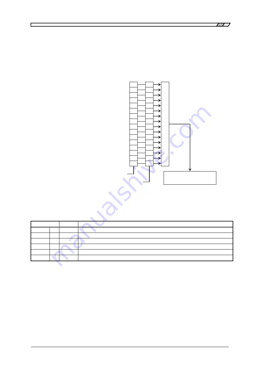
The structure of the overload status is illustrated in Figure 5-6.
The overload event register shows the I/O status of the
FRA5014
, as is shown in Table 5-6.
When “1” is set to bits in the overload event enable register, the corresponding bits in the overload
event register become valid, and when “1” is set to a valid bit, “1” is set to the OVE bit in the status
byte.
Figure 5-6. Structure of Overload Status
Table 5-6. Contents of Overload Event Register
Bit
Weight
Description (“1” when specified status is set)
CH4
4
16
Overload input was detected at CH4 (ERROR lamp is ON)
CH3
3
8
Overload input was detected at CH3 (ERROR lamp is ON)
CH2
2
4
Overload input was detected at CH2 (ERROR lamp is ON)
CH1
1
2
Overload input was detected at CH1 (ERROR lamp is ON)
OUTP
0
1
Oscillator’s output current is over the allowable range (ERROR lamp is ON)
Other
−
−
Always 0 (not being used)
Always 0 (not used)
Always 0 (not used)
Always 0 (not used)
Always 0 (not used)
Always 0 (not used)
Always 0 (not used)
Always 0 (not used)
Always 0 (not used)
Always 0 (not used)
Always 0 (not used)
Always 0 (not used)
CH4 over level (CH4)
CH3 over level (CH3)
CH2 over level (CH2)
CH1 over level (CH1)
Output overload (OUTP)
15
14
13
12
11
10
9
8
7
6
5
4
3
2
1
0
15
14
13
12
11
10
9
8
7
6
5
4
3
2
1
0
OR
OVER (overload event register)
OVEE (overload event enable register)
Overload event
status summary
Status byte’s OVE (bit 0)
Summary of Contents for FRA5014
Page 1: ...NF Corporation SERVO ANALYZER FRA5014 Instruction Manual...
Page 2: ......
Page 3: ...SERVO ANALYZER FRA5014 Instruction Manual DA00019832 004...
Page 10: ...Contents FRA5014 vi 8 7 General Items 8 6...
Page 26: ...2 2 Installation FRA5014 2 8 Figure 2 5 Removal of Feet...
Page 30: ......
Page 48: ......
Page 96: ......


