background image


NIO200 HAG User Guide


Page 78 of 120 

Channel: 

Displays current channel using. 

Bitrate:

 Displays current wireless data rate. 

BSSID:

 Displays MAC address of this radio


Encryption: 

Displays current encryption setting. 


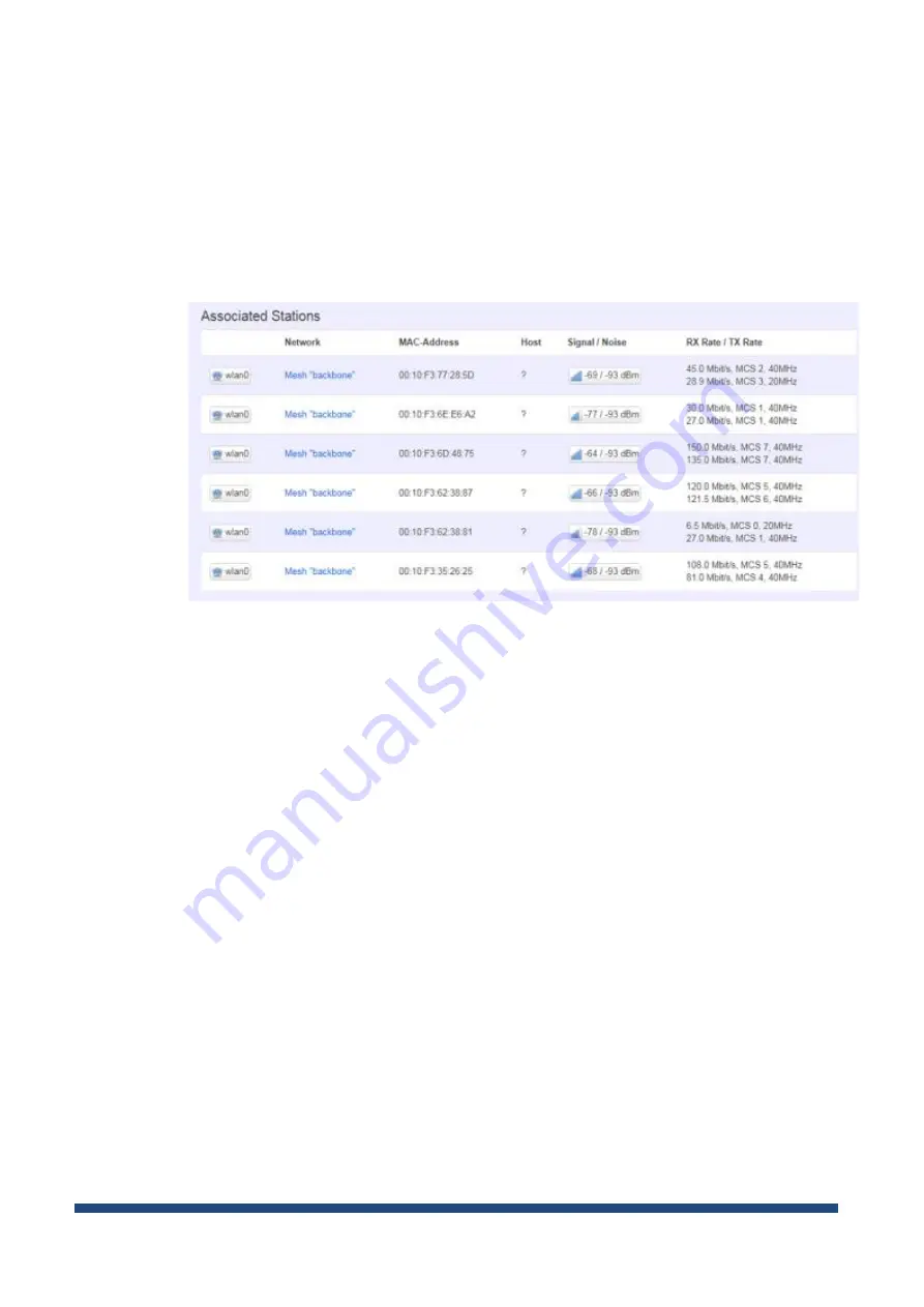
Associated Stations 


Displays current associated device information (Personal Computers or electronic devices) 

with NIO200HAG

, including device’s MAC address, signal level, noise, connecting data rate.


Summary of Contents for NIO200 HAG

Page 1: ...NIO200 HAG WirelessHART All in One Gateway User Guide Version 1 2 Date March 17 2017 ...

Page 2: ...NIO200HAG 8 3 2 Connect Wi Fi Antennas 8 4 Getting Started 9 4 1 NIO200HAG Gateway 9 4 2 Connecting to the NIO200HAG Gateway 9 4 3 Accessing NIO200 Admin website 9 4 4 Configuring the IP Address 10 4 5 Configuring the NTP settings 11 4 6 Monitoring Control System 11 5 Home page 13 6 Administration for the Network Devices 14 6 1 Dashboard 15 6 2 Topology 17 6 3 Devices 21 6 4 Device Details 24 6 5 ...

Page 3: ...Messages 52 7 6 2 Variables 53 7 6 3 Triggers 55 7 6 MODBUS 56 7 6 1 Mapping Registers 57 7 7 Advanced Settings 60 7 6 2 Edit Configuration Variables 60 7 6 3 Restart 62 7 6 4 Access NEXCOM NIO200 admin website 62 8 System Status 63 9 Administration 65 9 1 System Upgrade 65 9 2 Custom Icons 66 9 3 Custom Settings 67 9 4 Device Codes 68 9 4 1 Adding a Device Code 69 9 4 2 Editing a Device Code 69 9...

Page 4: ...ated Stations 78 2 2 Firewall 79 2 3 Routes 79 ARP 79 Active IPv4 Routes 79 Active IPv6 Routes 80 IPv6 Neighbors 80 2 4 System Log 81 2 5 Kernel Log 81 2 6 Processes 82 2 7 Real time Graphic 82 Load 83 Traffic 83 Wireless 84 Connections 86 3 System 87 3 1 System 87 General Settings 87 Logging 88 Language and Style 88 3 2 Administration 90 Router Password 90 SSH Access 90 ...

Page 5: ...Interfaces 95 4 2 Wi Fi 101 Associated Stations 102 Wireless configuration 102 Mesh Advanced 107 4 3 DHCP and DNS 109 General Settings 111 Resolve and Hosts Files 111 TFTP Settings 112 4 4 Advanced Settings 113 4 5 Hostnames 114 4 6 Static Routes 115 4 7 Diagnostics 117 4 8 Firewall 118 General Settings 118 Port Forwards 119 Traffic Rules 119 Custom Rules 120 ...

Page 6: ...ns Acronyms and Abbreviations The following table lists definitions acronyms and abbreviations that are only suitable to this document Term Description AP Access Point CSV Comma Separated Values A method to store data that is separated by comma so that it can be easily read and processed by Win32 and Unix programs GW Gateway Hop A hop describes the data being passed from one device to another as a...

Page 7: ...ol the processes that take place in the network 2 2 Logical Interfaces Interface Description Serial Port The serial port is used as a kernel console and emergency backup TCP The NIO200HAG Gateway accepts the following TCP connections The NIO200HAG Gateway has an http server listening on port 80 The NIO200HAG Gateway has an http server listening on port 8080 The NIO200HAG Gateway has an https serve...

Page 8: ... PoE facility such PoE swtich or PoE injector If use external DC power source please carefully check if the polarity of power cord fits the polarity drawing in this diagram When use PoE power source just plug in the Ethernet cable If the power connects correctly then the Power LED will lit accordingly 3 2 Connect Wi Fi Antennas ...

Page 9: ... address 192 168 1 1 for connection directly to a computer In order to communicate with the NIO200HAG the user must temporarily set the computer IP address to a static address 192 168 1 100 for example and may use an Ethernet cross over cable to connect the NIO200HAG to the computer 4 3 Accessing NIO200 Admin website Once the communication has been established with the NIO200HAG the user can log i...

Page 10: ...NIO200 HAG User Guide Page 10 of 120 4 4 Configuring the IP Address The IP Address can be changed in Network Interfaces page The user must click Save or Click Save and Apply when done ...

Page 11: ...ole is fulfilled by the Network Manager through the NTP application running on the device 4 6 Monitoring Control System WIRELESSHART specific network management and configuration takes place into the Monitoring Control System MCS Steps to access the MCS Step Action 1 Open the following URL http NIO200HAG_IP 8080 replacing NIO200HAG_IP with NIO 200HAG Gateway IP Once the address is accessed the log...

Page 12: ...NIO200 HAG User Guide Page 12 of 120 Figure 1 ...

Page 13: ...red and access is granted the browser will display the Device List by default Figure 2 The user interface consists of two sections The menus on the left which allow you to navigate through the pages of the website The main section which displays the contents of the selected page ...

Page 14: ...NIO200 HAG User Guide Page 14 of 120 6 Administration for the Network Devices The Network section provides information about various network tasks accessed from the Monitoring Control System Webpage ...

Page 15: ...sual representation of the information published by selected devices on selected channels The information is refreshed automatically at regular intervals 10 seconds 30 seconds or 1 minute To delete a device from the dashboard click in the top right corner of the pane No confirmation is required for the system to delete the pane To add a device to the dashboard perform the following steps Step Acti...

Page 16: ... range a message on the pane will notify you 5 Optional select the Slot number up to the current slot number if you do not select a slot number the system automatically assigns the next available slot 6 Select the desired Gauge type 7 Click OK to add the device to the dashboard NOTE You can also add a reading to the dashboard from the Device Details page in the Information pane click the Add to da...

Page 17: ... page To view the latest topology press Refresh The registered devices are displayed on multiple levels represented as grey bands The levels are numbered from 0 to n where n is a natural number The level number is indicated in the upper left corner of a level The Gateway the Network Manager and the Access Point are found on level 0 For the field devices the level represents the number of hops from...

Page 18: ...4 address They can be moved freely within the range of their level by drag and drop to obtain better legibility of the topology In addition they are represented by suggestive icons and against backgrounds of different colors to distinguish their roles Gateway purple background Access Point light green Network Manager dark green Field devices blue By positioning the cursor over an icon you can view...

Page 19: ...icular device click on that device in the topology graph or select the device in the drop down list located on top of the Topology pane 2 To view all the other links formed between the network devices check the Show all links option This option is unchecked by default 3 To view the RSQI signal values next to each link check the Show signal quality option For more information about the signal see s...

Page 20: ...rvice select it in the list There are four types of services which are represented by differently colored lines Blue for publish services Red for event services Green for maintenance services Black for block transfer services The Services legend located in the lower right corner of the Topology page also indicates how the types of services and links are represented Note A device can have multiple ...

Page 21: ...inkFlag indicates if selected device is the destination of the communication If both SourceFlag and SinkFlag are set indicate a bidirectional communication between selected device and the destination of service IntermittentFlag indicates if the service is used for acyclic intermit communication Period the frequency for generating packets for cyclic communication burst messages RouteID the ID of th...

Page 22: ...ld and click Search For partial search a Type part of the EUI 64 address in the EUI 64 Address input field b Select the desired state from the Show Devices drop down list and click Search The system will retrieve all the devices whose EUI 64 addresses contain the characters provided by the user To delete the search parameters click Reset 2 Search by device tag A tag is a custom description that yo...

Page 23: ...and is ready to operate Unregistered the device has lost connection with its neighbors in the network 6 3 2 Device List The Device list shows the network devices in a table one item per line with main information about each logical device EUI 64 address the MAC address Nickname the short address Device tag Device role Gateway Network Manager Access Point Field Router and model manufacturer informa...

Page 24: ...e you have the option of deleting an unregistered device When you delete a device it will be removed from the network and any related data including previous readings will be deleted from the database To delete the device click the icon located next to the device The system will require confirmation to perform the action Click OK to delete the device or Cancel to abort the action 6 4 Device Detail...

Page 25: ...ufacturer Model the model type of the device Revision the radio firmware version Power Status not available in the current version Data transmission statistics the number of transmitted received packages and the number of failed transmissions receptions Burst messages the definition of burst messages that the device will publish to the Gateway Burst messages Burst messages are used to publish data...

Page 26: ... Device Variable Classification Codes from HCF_Spec 183 specification document Unit Code will have one of the values described in Common Table 2 Engineering Unit Codes from HCF_Spec 183 specification document Update Period the value set through Command 103 at the configuration of burst message Max Update Period the value set through Command 103 The total number of rows in the table is indicated in...

Page 27: ...ce type publish event maintenance block transfer Is Source indicates whether the selected device is the source of the communication Is Sink indicates whether the selected device is the destination of the communication Is Intermittent indicates whether the communication on the service in question is intermittent on not Period the publishing period on the service in question Route indicates the ID o...

Page 28: ...between the field device and the Network Manager and Route with ID 2 is the default route established between the field device and the Gateway Peer the destination device which is either the Gateway or the Network Manager Graph the ID of the graph used by the route only for graph routes Is Source Path indicates whether the route is a source route Source Path for a source route it indicates the hop...

Page 29: ...e the Search functionality to view the behavior of the device over a specific period time Choose the status you wish to view from the Registration Status drop down list Optionally fill in the Start time and the End time fields and then click Search The results are displayed in a table that indicates the timestamp and the device status at that specific timestamp A device can have one of the followi...

Page 30: ...ntrols in the top right corner of the table also enable you to navigate through the other pages of the table 6 4 4 Neighbors Health This pane provides a communication health report about the selected device s neighbors The report includes Neighbor identification information the EUI 64 address The timestamp of the report request Flags this column indicates whether or not the neighbor is a clocksour...

Page 31: ...isplayed per page in the table The default number is 10 Paging controls in the top right corner of the table also enable you to navigate through the other pages of the table 6 4 5 Schedule Report The schedule report pane provides information about time slot and channel allocation for the selected device Superframes and links The superframes that the device uses for communication are listed in the ...

Page 32: ...ks allocated on each superframe Clicking on the number of links will display a new page with link related information for each individual link allocated on the selected Superframe as shown in the following screen The following details are shown Nickname of the neighbor the short address of the neighbor or the broadcast address FFFF FFFF FFFF FFFF used only for advertisements and receive links ...

Page 33: ...type which can be o Normal o Broadcast o Join o Discovery You can use the search form on the top of the page to sort links based on the nickname of the neighbor device and the link type In addition in both the Superframes and Links tables you can view the information by the number of items listed per page The default number is 10 Paging controls at the bottom of the table enable you to navigate th...

Page 34: ...d service list 782 read session list etc To generate the command follow the steps described below 1 Select the WH General Commands set from the Command drop down list 2 Optionally select the BypassIOCache value Yes if you wish to retrieve the response to the command directly from the device No if you wish to obtain the response from the Gateway cache If you do not select a value the default value ...

Page 35: ...tatistics and device specific communication health information In the network summary section the following information is indicated Devices Count the total number of registered devices including the Access Point Join count the total number of joins of all the devices in the network Start Date the date and time the Network Manager application was started Current Date the present time Transmission ...

Page 36: ...ted All devices will report 0 Nominal Generated the number of packets generated by the device All Tx all the packets transmitted but the selected device including for routing purposes No ACK the number of packets that require acknowledgement and which were sent by the selected device but not acknowledged by the destination device Terminated the number of packets received by this device as a destin...

Page 37: ...commands or by automatic burst messages The readings can be filtered by device variable name command number or the device variable code To search for readings select a device or fill out the input fields as desired and click Search The results are displayed in a table that contains the following information for each reading Device EUI 64 address MAC address of the device that reported the reading ...

Page 38: ...r of items to be displayed per page in the table The default number is 10 Paging controls in the top right corner of the table also enable you to navigate through the other pages of the table From this page you can also save the search results into a Microsoft Excel CSV file by clicking Export 6 7 Commands Log In this page you can view all the commands issued on the registered devices in the syste...

Page 39: ...e response for the issued command if the command was responded successfully or the error reason if the command failed which can consist of o System generated commands success or the hex value representing the response payload if any in case of success Error code and reason in case of command failure o WH General Command two bytes representing the command code followed by one byte representing the ...

Page 40: ...Search dialog and click Search The total number of rows in the table is indicated in the top left corner of the table Here you can set the number of items to be displayed per page in the table The default number is 10 Paging controls in the top right corner of the table also enable you to navigate through the other pages of the table From this page you can also save the search results into a Micro...

Page 41: ...y and type Class of alert Optionally fill in the Start time and the End time fields and then click Search The results are displayed in a table that indicates the following information The device tag The device nickname EUI 64 address the MAC address of the device generating the alert Alert Time the date and time when the alert condition was detected Alert Type o Path Down when the device s path to...

Page 42: ... peer Peer ID Graph ID the nickname of the neighbor peer or graph depending on the type of alert MIC the MIC value of the packet that failed routing on a source route that failed You can set the number of records to be displayed per page in the table The default number is 10 Paging controls at the bottom of the table allow you to navigate through different pages of the search results From this pag...

Page 43: ...tise therefore they should be carefully planned as any inconsistencies may render the devices network inoperative NOTE The changes you perform in the settings for each separate entity will also be reflected in the Advanced Settings page and vice versa 7 1 Access Point The Access Point configuration page consists of 4 sections as shown is the image below On hover over an edit box a tooltip will app...

Page 44: ...Under Serial communication provide the name of the serial port Under Logging Select the application and stack logging level The numbers suggest the degree of detail provided in the Access Point logs o 1 ERROR for error messages only o 2 WARN for error and warning messages o 3 DEBUG for error warning and debug messages When you have finished editing the settings click Save As mentioned previously d...

Page 45: ...ay optional and the timeout period in seconds for cache read response and cache burst response Note If you change any of these settings you must restart the Gateway in order for the new settings to take effect Under Provision security Specify the Join key Note If you change any of these settings you must restart the Gateway in order for the new settings to take effect Under Logging ...

Page 46: ... error warning and debug messages When you have finished editing the settings click Save As mentioned above depending on the settings that you modify the Access Point may need to be restarted for the changes to take effect 7 3 Network Manager The Network Manager configuration page consists of 3 sections as shown is the screen capture below On hover over an edit box a tooltip will appear indicating...

Page 47: ...ble Disable Compatibility Mode for the old Emerson devices starting with revision 2 Enable Disable Dynamic Management Bandwidth for the Network Manager to dynamically adjust devices bandwidth Under Channel maps Enable the desired frequency channels for communication with the network devices for each Network ID Click Add for a new Network ID or to remove it If you are using more than one Network ID...

Page 48: ...rrect values may render the devices dysfunctional or may cause difficulty to trace malfunctions Click Help in the upper right corner of the window to view information and examples of the accepted data formats in all the sections Notes 1 The EUI 64 address is unique in a network 2 All the devices in a network must have the Network ID of one of the Access Points When adding a device you have the pos...

Page 49: ...to the Access Points list To edit an Access Point 1 Click on the entry that you want to edit in the Access Points list 2 Edit the security key and or Network ID and click Save to save the changes in the whart_provisioning ini file Considering Note 1 above if you change the EUI64 address of an existing Access Point the Network Manager will recognize it as a new entity and will add the new Access Po...

Page 50: ... and click Save to save the changes in the whart_provisioning ini file After you edit the Gateway section click Activate to load the changes into the Network Manager The changes will be visible in the network topology and where applicable in the device list 7 4 3 Configuring Devices Adding devices You can add devices either individually one device at a time or you can add multiple devices at a tim...

Page 51: ...ist Loading a List of Devices You can add multiple devices at the same time by importing them from a file The file will contain a list of devices with the EUI64 Key and NetworkID when appropriate comma separated values To load a list 1 Click on Browse to locate the text file that you wish to load and click Upload 2 Click Activate to load the new device list into the Network Manager The current wha...

Page 52: ...n was not manually entered in Monitor_Host_Publishers conf file or a discovery process was not ran previously filling the appropriate settings in the file Click Help in the upper right corner of the window to view information and examples of the accepted data formats in all the sections 7 6 1 Burst Messages To add a burst message definition 1 In the empty edit box type the parameters of a burst me...

Page 53: ...hange the EUI64 and burst message index into that of the new burst message 3 Change other parameters if applicable 4 Click Save The burst message will be added to the list the variables and triggers of the original burst message are preserved in the newly added burst message To edit a burst message 1 In the burst message list click on the entry that you want to edit 2 Edit the desired parameters a...

Page 54: ...3 the units code see Common Table 2 and Command 4 required for commands 3 9 and 33 The command number and burst message index are the same as those used in the burst message definition and are not editable in the interface 2 Click Save The variable will be added to the variables list for that specific burst message and the changes will be saved in the Monitoring Host configuration file To edit a v...

Page 55: ...rface 2 Click Save The trigger will be added for the selected burst message and changes will be saved in the Monitoring Host configuration file To edit a trigger 1 In the trigger edit box edit the desired parameters and click Save The changes will be stored in the Monitor_Host_Publishers conf file To delete a variable 1 Click Delete button near the trigger edit box 2 You will be asked for confirma...

Page 56: ...Publishers conf file will be overwritten Exporting the Burst Message Definitions This page also enables you to export the publisher list including channels by clicking Download in the Manage burst messages list section 7 6 MODBUS This section enables you to map WIRELESSHART attributes to Modbus registers Click Help in the upper right corner of the window to view information and examples of the acc...

Page 57: ... data element EUI 64 string of 16 hex digits representing the 8 bytes of a device s EUI 64 address register type device_variable gw_info or gw_code_word are the three register types supported When register type is device_variable the following parameters must be specified the burst message you want to map device variable code device state decimal integer 0 and 2 with the following meaning o 0 the ...

Page 58: ...osed Observation start_addr 0 Number of devices currently 16bit big endian integer connected start_addr 1 Total number of burst messages 16bit big endian integer start_addr 2 Versa Router MAC 3 words 16bit big endian unsigned integer Note For register type gw_info the word_cnt must be 5 When register type is gw_code_word the gateway s code word will be exposed to Modbus The code word is read only ...

Page 59: ... of Modbus 16 bit registers in the Modbus addressing space to hold the entire data entity plus an additional Modbus register to hold the auto generated status if applicable When the chunk is bigger than the size of the data entity it will be filled with the actual data from the lowest addressed register to the highest and from the MSB of each register to the LSB If the data entity does not entirel...

Page 60: ...ost list into Modbus The current modbus_gw ini file will be overwritten Exporting the Registers This page also enables you to export the registers by clicking Download in the Manage registers list section 7 7 Advanced Settings 7 6 2 Edit Configuration Variables This page allows you to view set less common configuration variables which cannot be changed using the classic MCS web interface ...

Page 61: ...ion 1 The following form will open to the right of the operation list 2 In the form select a Section in the drop down list The Variable list will change accordingly 3 Select a Variable in the drop down list IMPORTANT Do not change GLOBAL AN_ID under any circumstance 4 Set edit the Value field then click Set 5 To add a new variable select Custom under Variable type The Sections variables form will ...

Page 62: ...AG Gateway NOTE After restarting the applications or rebooting the NIO 200HAG Gateway the Monitoring Control System becomes inoperative for a few minutes After Stopping the applications the Monitoring Control System becomes inoperative until the next power cycle 7 6 4 Access NEXCOM NIO200 admin website This section allows the user to navigate to NEXCOM NIO200 admin website where the NIO200 Network...

Page 63: ...and load average on the NIO 200HAG Gateway The System Status page displays statistical information regarding processor and memory usage and load average on the NIO200 The first five sections indicate the status Running or Not Running memory usage and processor usage for the Access Point Gateway Network Manager MODBUS and Monitor Host processes ...

Page 64: ...s The system s load average over the past one five and fifteen minutes respectively The number of running processes out of the total number of processes The ID of the last started process If you wish to regularly update the system status information enable the Auto refresh page option at the bottom of the page The page will auto refresh at one minute intervals ...

Page 65: ...System Upgrade The System Upgrade page enables you to upgrade the system components hosted on the connected NIO 200HAG Gateway The Firmware form indicates the current system version on the NIO 200HAG Gateway To initiate the upgrade Step Action 1 Click Browse to locate and open the upgrade package that you wish to use 2 Click the Upload Firmware button to initiate the process 3 Make sure the NIO200...

Page 66: ...oaded the existing custom icons are displayed in a table with the following information Model the device model Role the device role Icon shows the existing picture The default icons are not listed To add an icon 1 Click the Add Icon button The Custom Icon form will open 2 Select the Device Model Role from the drop down list 3 Click Browse to locate the icon you want to use The maximum icon size mu...

Page 67: ...ed for confirmation Click OK to delete the icon or Cancel to abort the action Note When you delete an icon it will be automatically replaced with the def ault icon for the selected device model role in the Topology and Devices pages 9 3 Custom Settings This page enables user to define whether the timestamps get shown using browser local time zone or UTC and enable disable various high side interfa...

Page 68: ...e as given by the vendor Company the device vendor When a new device joins the Nivis WirelessHART network and reports a device code that is not part of the list the new device code will be automatically added to the list having the Model and Company fields populated with N A You must change the model and company names manually To learn how to change these fields see section Editing a Device Code Y...

Page 69: ...s that match your search criteria If no entries match your selected criteria the system will display the message No records 9 4 1 Adding a Device Code To add a device code 1 Click the Add Device Code button located on top of the search form The Add Device Code form will open 2 In the form fill in the edit fields with the desired information 3 Click Save to add the device to the list or Back to can...

Page 70: ...d add it again 3 Click Save to save your changes or Back to cancel the action and return to the Device Codes page 9 4 3 Deleting a Device Code To delete a device code click the icon located next to the corresponding entry in the table The system will require confirmation to perform the action Click OK to delete the device code or Cancel to abort the action Note When you remove a device from the De...

Page 71: ...e New password field 3 Retype the new password in the Confirm new password field for verification NOTE The passwords are case sensitive 4 Click Save at the bottom of the page to save the new password which will become your current password Tip To prevent unauthorized persons to gain access to your account use a strong password in order to make it difficult for others to determine it and do not dis...

Page 72: ...NIO200 HAG User Guide Page 72 of 120 Appendix Advanced configuration about Wi Fi features ...

Page 73: ...you may open a browser to access the Web GUI via default IP address 192 168 1 1 The login Web page requires login information as below Default login information is Login root Password admin After successful login you will see the Status page of the device Web UI Saving Changes ...

Page 74: ...r you do the changes at the bottom of WebUI Unsaved Changes UNSAVED CHANGES provides the help to see the parameters which were not saved applied Click Save Apply button to save the parameters Auto Refresh Toggle AUTO REFRESH button to turn on off WebUI refresh function automatically ...

Page 75: ... Real time Graphs from the pull down list like below screen 2 1 Overview To see NIO200 over all status click Overview to displays the current system information and interface connection status System Hostname Displays NIO200 host name Model Displays NIO200 HW basic information Firmware Version Displays NIO200 firmware version Kernel Version Displays NIO200 Kernel version Local Time Displays NIO200...

Page 76: ... past 1 minute 43 in the past 5 minutes 24 in the past 15 minutes Memory Total Available Displays the available memory in percentage Free Displays free memory of NIO200 Buffered Displays buffer memory used in the system Network IPv4 WAN Status Displays current connecting IPv4 information IPv6 WAN Status Displays current connecting IPv6 information Active Connections Displays current active connect...

Page 77: ... including IPv4 MAC address and leasing time DHCPv6 Leases This displays information about hosts Personal Computers or electronic devices that are connected to NIO200 including IPv6 DUID and leasing time Wireless This displays Wireless information about NIO200 for radio 0 1 SSID Displays the name of the wireless network Mode Displays the mode in this radio ...

Page 78: ... wireless data rate BSSID Displays MAC address of this radio Encryption Displays current encryption setting Associated Stations Displays current associated device information Personal Computers or electronic devices with NIO200HAG including device s MAC address signal level noise connecting data rate ...

Page 79: ...vice with sophisticated and specifically defined parameters in this Web page It s highly recommended to keep this Firewall setup page as it is 2 3 Routes This section display information about routing list for current connecting device ARP Displays APR table information of NIO200 including IPv4 address MAC address and connecting interface Active IPv4 Routes ...

Page 80: ...NIO200 HAG User Guide Page 80 of 120 Displays active WAN and LAN port s IPv4 routing table Active IPv6 Routes Displays active IPv6 routing table of WAN and LAN port IPv6 Neighbors ...

Page 81: ...00 HAG User Guide Page 81 of 120 Display connected device with IPv6 information 2 4 System Log The System Log Web page contains the events log in NIO200 system for trouble shooting reference 2 5 Kernel Log ...

Page 82: ...oting status monitoring by professional personnel in the field Any improper terminating or killing individual process tasks may cause device malfunction It s highly recommended to keep this Firewall setup page as it is 2 7 Real time Graphic This section provides utilities to monitor NIO200 system information including real time load real time Ethernet traffic Real time wireless signal and real tim...

Page 83: ... To monitor status in this section please make sure WebUI auto refresh function must be turn on Load Display real time CPU average loading percentage i e 1 minute Minimum 8 Average 8 Peak 33 5 minutes 33 33 39 15 minutes 34 34 36 Traffic ...

Page 84: ... 84 of 120 Display NIO200 real time traffic loading of Ethernet WLAN and internal bridge interfaces Inbound Incoming data throughput of the observed interface Outbound Outgoing data throughput of the observed interface Wireless ...

Page 85: ...age 85 of 120 Display Wireless real time signal quality including signal level noise and data rate wlan0 Radio0 information wlan1 Radio1 information Note There will be no radio information when the WLAN interface is disabled ...

Page 86: ...NIO200 HAG User Guide Page 86 of 120 Connections This Connections displays NIO200 real time active TCP UDP ICMP connection information for trouble shooting reference ...

Page 87: ...ll down list like below screen 3 1 System General Settings This section provide general settings of NIO200 including Time Host name Time zone and NTP Click Sync with browser let NIO200 sync time with your computer And select country from the pull down list in the Timezone To make NIO200 system get time synchronization with NTP server user may enable the NTP client and input the address of an NTP s...

Page 88: ... of external log server External system log server port The port number of external log server Log output level The output information of log including Debug Info Notice Warring Error Critical Alert and Emergency Cron Log Level The minimal level for cron messages to be logged to syslog Language and Style This section provides setting of language and WebUI style NIO200 only provides English as defa...

Page 89: ...NIO200 HAG User Guide Page 89 of 120 ...

Page 90: ...l SSH Enable NIO200 to be accessed via SSH based application This increase the security in configuration of NIO200 remotely Interface Select the interface Port Enter the port number for the communication via SSH Password authentication Enable Disable SSH password authentication Allow root logins with password Enable Disable the root user to login with password ...

Page 91: ...e for additional SSH public key authentication 3 3 Backup Flash Firmware To upgrade new firmware on device user may choose Backup Flash Firmware from Systme in tool bar as below Upgrade Firmware To flash a new firmware image to NIO200 user may press the button of Flash image as below ...

Page 92: ...u can choose Proceed to start the upgrading Note After you click Proceed the DUT firmware will be upgraded with the file you selected and the upgrade progress will display like below Note The whole firmware image may take several minutes to complete the flash writing PLEASE DO NOT REBOOT OR POWER OFF THE DEVICE before the whole progress ...

Page 93: ...below Then save it as a file in your PC To restore previous configuration user need to browse the backup file and then press Upload archive button as belwo Note After restore the file system will apply the changes and automatically reboot Due to configuration backup may cause IP address change you have to enter new IP address accordingly Otherwise the new web page may not be accessible Reset to de...

Page 94: ...take several minutes to complete PLEASE DO NOT REBOOT OR POWER OFF THE DEVICE before the whole process being successfully done 3 4 Reboot Click the Perform reboot button will help to warm start the system After system finish reboot process it will back to Login page ...

Page 95: ... a new IP address please click Network from page bar then select the Interface and then click Edit Edit IP address When modifying the IP address user needs to input the IP address netmask gateway for this device and then click Save Apply to save this new IP address into flash and apply it immediately ...

Page 96: ...tting or LAN port group settings Delete Delete this Interfaces from group Note Do not perform Stop LAN interface when this is the only available interface otherwise the system will not be able to work Under such condition please press the button longer than 10 sec to get system back to factory default setting User can go on the configuration with defult IP address 192 168 1 1 WAN LAN Interface ove...

Page 97: ...n if you do not have a DHCP server in your network or if you wish to assign a static IP address to NIO200HAG DHCP client When Dynamic IP DHCP is selected the DHCP client to be functional once this selection is made Unmanaged This Interface have no configuration interface or options PPP For old serial modem provided point to point link for NIO200HAG PPPoE For cable modem or ADSL user link NIO200HAG...

Page 98: ...NIO200 HAG User Guide Page 98 of 120 Advanced Settings This is used for advanced settings and configure strongly recommend user do not make change to this web page Physical Settings ...

Page 99: ... WAN or LAN interface Normally only LAN interface need to enable bridge interfaces After enable bridge interfaces select interfaces to bridge Interface Select interfaces for your bridge group Select both the Ethernet adapter most likely eth0 1 eth1 and the wireless network DHCP Server General Setup ...

Page 100: ...ou will need static IP or another DHCP server for your network interfaces Default is enable DHCP Advanced Settings Dynamic DHCP Dynamically allocate DHCP addresses for clients If disabled only clients having static leases will be served Force Force DHCP on this network even if another server is detected ...

Page 101: ...terfaces status Wireless Overview includes channel SSID MAC address and security setting information Scan Scan can explore how many AP signals can be detected This is a good way to get the idea about how noisy the installation site is User can choose a channel which is less interference with other APs Add Add new virtual AP in the same radio interface You will see new interface after click add ...

Page 102: ...nterface Associated Stations Associated stations show wireless client connection information It includes the SSID wireless client connect wireless client MAC IP address RSSI signal strength and Tx Rx rate Wireless configuration Please select network Wi Fi and click Edit to configure Radio0 or Radio1 The Device Configuration section covers physical settings of the radio hardware such as channel tra...

Page 103: ...rface Operating frequency Select radio frequency and channel bandwidth for signal transmission For channel bandwidth please note you need to confirm AP client mode or mesh mode and which channel you will use Transmit Power Control the transmit power of a radio by selection of Transmission Power Advanced settings ...

Page 104: ...etwork performance Only minor modifications of this value are recommended RTS CTS Threshold Default off RTS CTS Request to Send Clear to Send is the optional mechanism used by the 802 11 wireless networking protocol to reduce frame collisions introduced by the hidden node problem RTS CTS is an additional method to implement virtual carrier sensing in Carrier sense multiple access with collision av...

Page 105: ... Key WEP provides a basic level of security preventing unauthorized access to the network and encrypting data transmitted between wireless clients and an access point WEP uses static shared keys that are manually distributed to all clients that want to use the network WPA PSK Clients using WPA for authentication WPA2 PSK Clients using WPA2 for authentication WPA PSK WPA2 PSK Mixed Mode Clients usi...

Page 106: ...NIO200 HAG User Guide Page 106 of 120 The cycle icon will display the characters you just input MAC filter Select MAC Filtering Specifies the MAC address to block or allow traffic from ...

Page 107: ...ity High After continuous 2 seconds with signal level higher than Block threshold the blocked Mesh link can be available again After continuous 2 seconds with signal level lower than Block threshold the active Mesh link will be blocked Medium After continuous 5 seconds with signal level higher than Block threshold the blocked Mesh link can be available again After continuous 5 seconds with signal ...

Page 108: ...e implies more frequently used in data forwarding by Mesh network Too long inactive time means the Mesh path is almost un used Signal display the dynamic RSSI signal strength when refresh State display the current status is ESTAB established or BLOCKED blocked When BLOCKED implies the signal strength is too low to use in data forwarding Dest addr Next hop When Dest Destination MAC address and Next...

Page 109: ...re are four categories of settings or lease status Active DHCP Leases Active DHCPv6 Leases Static Leases and Server Settings Scroll to the following screen in the DHCP and DNS window This screen displays the lease information to which DHCP server assigns automatically including Hostname IP address MAC address or DUID and Remaining Lease time DUID stands for the DHCP Unique Identifier Please look a...

Page 110: ... a corresponding lease are served Add Add a new lease entry After clicking Add button a new entry with 4 blank input boxes will appear Allow users to fill in the information such as The MAC Address identifies the host the IPv4 Address specifies the fixed address to use and the Hostname is assigned as symbolic name to the requesting host Delete delete the followed entry Scroll to the screen identif...

Page 111: ...NIO200 HAG User Guide Page 111 of 120 General Settings Domain required default value is checked Authoritative default value is checked Resolve and Hosts Files ...

Page 112: ...NIO200 HAG User Guide Page 112 of 120 TFTP Settings By default TFTP server is not enabled ...

Page 113: ...NIO200 HAG User Guide Page 113 of 120 4 4 Advanced Settings Max DHCP Leases default value is unlimited Max concurrent queries default value is 150 ...

Page 114: ... the Hostnames page For those device does not have hostname or does not resolve automatically users manually assign hostname IP pair to specific devices Add create a host entry hostname IP pair for a specific device For example Hostname Test Device IP address 192 168 1 251 Delete delete the followed host entry ...

Page 115: ...st or network can be reached over Such pair interface and gateway is called route For IPv4 network scroll down to Static IPv4 Routes screen as follows Add add an entry for route to an IPv4 network or host For example Target network 192 168 10 0 Netmask 255 255 255 0 NIO200HAG WAN IP 192 168 0 1 The route to be assigned will be wan for interface and 192 168 0 253 for gateway Leave Metric and MTU fi...

Page 116: ...e Page 116 of 120 Delete delete a followed route entry For IPv6 network scroll down to Static IPv6 Routes screen as follows Add add an entry for route to an IPv6 network or host Clicking Add button has an entry as follows ...

Page 117: ...host on an Internet Protocol IP network and measure the round trip time for messages sent from the originating host to a destination host and back The only required parameter is the name or IP address of the destination host Traceroute track the route packets taken from an IP network on their way to a given destination host The only required parameter is the name or IP address of the destination h...

Page 118: ...ration including General Settings and Zones categories In the General Settings category there are 5 basic options for traffic control over interfaces Enable SYN flood protection default enabled Drop invalid packets default disabled Input default accept Output default accept and Forward default reject In the Zones category users create or edit zones over your network interfaces to control network t...

Page 119: ...he tables for port forwarding Adding or editing specific forwarding table allows remote computers on the Internet to connect to a specific computer or service within the private LAN In the New port forward category there is only one button for flow editing Add create a new flow entry for port forwarding among zones Traffic Rules Clicking the Traffic Rules tab on the top of screen will appear the p...

Page 120: ...ined control over the source IP used for outgoing traffic For example to map multiple WAN addresses to internal subnets can be added or edited Add and edit create a new entry with default values and edit at once if required Please remember clicking Save Apply button to activate the new settings Custom Rules Custom rules allow you to execute arbitrary iptables commands which are not otherwise cover...

Reviews: