NP727 User’s Manual V1.00
3.
Installation
3.1 Panel Function Description
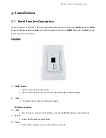
On the front panel of the NP727, there are three LEDs that are used to indicate the
POWER
status, the
WLAN
status, and the link status of the
LAN
port. On the front panel, there are: one
RESET
button and one
LAN
port. The
antenna is built-in chip antenna.
Front Panel
1.
RESET Button:
¾
Press the button to restart the system.
¾
Press the button for more than 30 seconds to reset the system to default settings.
2.
LAN:
¾
The LAN port is for connection with wired networks.
LED status indication:
3.
LAN
¾
OFF indicates no connection; ON indicates connection; BLINKING indicates transmitting data.
4.
WLAN
¾
Green LED ON indicates system ready.
5.
Power
¾
Green LED On indicates power on; OFF indicates power off.
Summary of Contents for INFRASTRUCTURE SERIES
Page 1: ...NetComm INFRASTRUCTURE Series In wall Wireless Access Point USER GUIDE...
Page 3: ...NP727 User s Manual V1 00 4 5 3 Repeater Information 62 4 5 4 Event Log 61 4 6 Online Help 62...
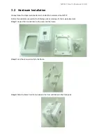
Page 13: ...NP727 User s Manual V1 00 Step 4 Cover it with faceplate...
Page 51: ...NP727 User s Manual V1 00 Layer 2 Firewall Overview Check State...


