Neptune 13458-000 Installation And Maintenance Manual Download Page 74

Installing the UPS

To install the UPS, complete the following steps.

Figure 71  – UPS Mounted on a Wall

1. To mount the UPS to a wall near the Gateway, use

corrosion-resistant hardware through the four holes

provided in the mounting bracket. See Figure 71.

The Gateway and UPS can be mounted directly to a wall or
strut channel that is attached to a wall.

The mounting brackets for the Gateway and UPS have the
same horizontal and vertical hole spacing. This allows you to
mount both of them on the same two pieces of the strut
channel. The two pieces of the strut channel can be mounted
horizontally (Gateway and UPS in a "side by side"
arrangement) or the strut channel can be mounted vertically
(Gateway and UPS in a "stacked" arrangement).

Be sure to mount the UPS in close proximity (within 3 feet) of
the Gateway

.

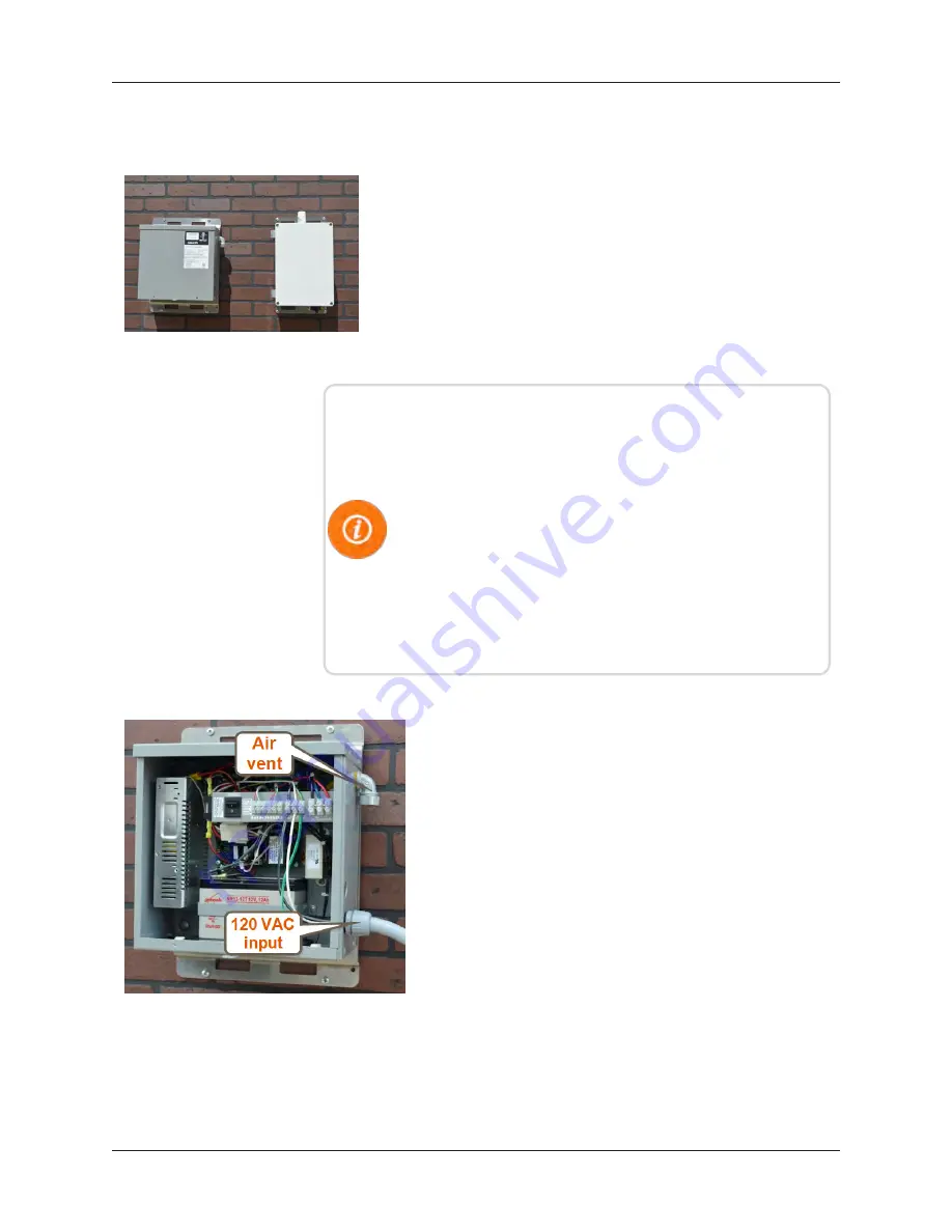
Figure 72  – UPS with VAC Input
Wired

2. Remove the two screws from the cover on the UPS, and

remove the cover.

3. Wire the 120 VAC input through the lower knockout

hole. See Figure 72.

56

R900 Gateway Installation and Maintenance Guide

Chapter 4: Installation of the Gateway

Summary of Contents for 13458-000

Page 1: ...R900 Gateway Installation and Maintenance Guide R900 Gateway v4 Installation and Maintenance Guide CE5320...

Page 2: ......

Page 3: ...R900 Gateway v4 Installation and Maintenance Guide...

Page 4: ...pment has been tested and found to comply with the limits for a Class B digital device pursuant to Part 15 of the FCC Rules These limits are designed to provide reasonable protection against harmful i...

Page 5: ...s exigences de l interf rence canadienne causant desr glements d quipement L op ration est sujette aux deux conditions suivantes 1 ce dispositif peut ne pas causerl interf rence nocive et 2 ce disposi...

Page 6: ...This page intentionally left blank...

Page 7: ...tallation 5 Gateway Kits 5 Solar Unit 5 AC Unit 6 Cellular Modem 6 Ethernet 6 Provisioning the Cellular Service to the Gateway 7 Chapter 2 Activating Gateway in the Host Software 9 Step One 9 Step Two...

Page 8: ...ions 25 Storage 26 Unpacking 26 Tools and Materials 26 Safety and Preliminary Checks 28 Chapter 4 Installation of the Gateway 29 Mounting RF Antenna to a Pole or Stand 29 Mounting the RF Antenna 30 Mo...

Page 9: ...Attaching Ground Wire 50 Attaching the RF Antenna Cable 50 Weatherizing the RF Antenna Connection 51 Connecting Power to the Gateway 51 Attaching the Power Cable 51 Configuring the Cellular Modem 52...

Page 10: ...Verifying Cellular Modem Power 74 Report Now Function 75 Still Not Operating Properly 75 Contacting Customer Support 75 By Phone 75 By Fax 76 By Email 76 Appendix A Solar Power Information 77 Install...

Page 11: ...onnects and Protections 90 Self Diagnostics Self Test 91 Terminate the Self Test 92 Select Battery Type 92 Additional Troubleshooting Information 93 Troubleshooting the Solar Panel s Battery 93 Solar...

Page 12: ...8 Provisioning the Vanguard 3000 for GSM 111 Modem Setup Troubleshooting 111 Cellular Modem Conversion Kit 111 Installing the Cellular Modem Conversion Kit 111 External Cellular Antenna Option 112 Ins...

Page 13: ...ew Collector Gateway Dialog 12 Figure 14 Collector Type 12 Figure 15 Select Type 12 Figure 16 Copy an Existing Gateway 13 Figure 17 Basic Information 13 Figure 18 Gateway Location 14 Figure 19 Static...

Page 14: ...Wire 37 Figure 44 Connector Hub 38 Figure 45 Battery Box Wires 38 Figure 46 Ground Wire 39 Figure 47 RF Antenna Cable 39 Figure 48 Power Cable 40 Figure 49 Concrete Block Ballast 41 Figure 50 Activat...

Page 15: ...Figure 74 Ground Wire 57 Figure 75 Adding Gateway Cables 58 Figure 76 Power Connector 58 Figure 77 UPS Power Switch 58 Figure 78 Wall Installation 59 Figure 79 Securing Pole Bracket 60 Figure 80 Linin...

Page 16: ...0 Figure 100 Gen 2 Solar Controller 84 Figure 101 Gen 3 Solar Controller 85 Figure 102 ProStar Controllers 88 Figure 103 ROHN JRM23855 Stand 100 Figure 104 Cellular Modem Front Status LEDs 109 Figure...

Page 17: ...4 Solar Power System Troubleshooting 82 Table 15 Charging Status LED Definitions 86 Table 16 Battery Status LED Definitions 86 Table 17 Charging Status LED Error Indications 87 Table 18 Battery Status...

Page 18: ...tallation Materials Needed 106 Table 34 CDMA Bands Speeds Supported by Vanguard 3000 107 Table 35 GSM Bands and Speeds Supported by Vanguard 3000 107 Table 36 Certifying Carriers by Nation 108 Table 3...

Page 19: ...t the Gateway This guide also provides information for configuring the cellular modem for the Gateway installing the solar power unit and ordering information for necessary cables and accessories Conv...

Page 20: ...site selection and detailed installation instructions Determining How to Install the Gateway Because of the risks involved to personnel and equipment Neptune recommends using qualified professional f...

Page 21: ...Gateway antenna mast or antenna to a pole or similar structures carrying open electric light power wires or trolley wires over 250 volts between conductors See NEC Article 8 10 See Appendix A The Gat...

Page 22: ...Gateway Wall Mount Installation The Gateway allows for a cellular modem or Ethernet connection for backhaul communication Gateway Stand The Gateway mounted on a stand can be either solar powered or AC...

Page 23: ...C The 12 VDC can be provided by a solar power system or Uninterruptible Power Supply UPS Solar Unit The solar version of the Gateway uses a solar power source in conjunction with a cellular modem or E...

Page 24: ...tative for details 2 Some installation sites have a weak cellular signal 90 dBm or weaker An optional external cellular antenna mounting kit Neptune Part No 13147 000 can increase the signal strength...

Page 25: ...such as GSM UMTS EDGE and GPRS Verify with the chosen cellular service provider 2 Identify the modem identification numbers from the Gateway International Mobile Equipment Identifier IMEI and Mobile E...

Page 26: ...This page intentionally left blank Chapter 1 Overview 8 R900 Gateway Installation and Maintenance Guide...

Page 27: ...b browser Step Two Determine whether to use an existing Gateway server or add a new one to the N_SIGHT PLUS host software If you want to use an existing Gateway server proceed to Step Three on page 11...

Page 28: ...enance Window The Table Maintenance window appears See Figure 9 Figure 9 Gateway Detail Window 4 Click the Create New Option button See Figure 10 The following dialog appears Figure 10 Table Details 1...

Page 29: ...ess Internal Type the internal Web address if different from above Accessible Select the Web service 6 Click Save Close Step Three Create a new Gateway record in N_SIGHT PLUS To create a new record co...

Page 30: ...ialog 3 Click Gateway See Figure 14 The following dialog appears Figure 14 Collector Type 4 Select V4 from the drop down menu See Figure 15 Figure 15 Select Type 12 R900 Gateway Installation and Maint...

Page 31: ...copy configuration settings No Allows you to build a new configuration Figure 16 Copy an Existing Gateway Basic Information 1 Click Next and the following dialog appears Figure 17 Basic Information R...

Page 32: ...t software Description Type reference name for location 5thStTank WTP1 Location 1 Click Next and the following dialog appears Figure 18 Gateway Location 2 Complete the required fields on the Location...

Page 33: ...atic IP Window 2 Select Yes or No l If No is selected go to Web Service on the next page l If Yes is selected click Next and the following dialog appears Figure 20 Static IP Details R900 Gateway Insta...

Page 34: ...ist for each of the following fields Field Option Select Web Host Select Web server name Select Web Service Host Backup Select Web server name Select Web Service Firmware Select same Web server Networ...

Page 35: ...22 Read Reporting 2 Leave all values set to zero Command Polling 1 Click Next and the following dialog appears Figure 23 Command Polling 2 Leave all values set to zero R900 Gateway Installation and Ma...

Page 36: ...that the fields have the following default values l Download Extension tar l Rename Extension xxx l Data Extension dat Advanced Options 1 Click Next and the following dialog appears Figure 25 Advanced...

Page 37: ...Keep Modem On field 5 Select 25000 as the value for the Max MIUs field 6 Click Finish and the Gateway is created The Collectors Search window appears See Figure 26 If the Finish button is not active s...

Page 38: ...e Installation of the Gateway on page 29 and Solar Power Information on page 77 in Appendix A 2 Open the Gateway If cellular modem activation is required see Cellular and Ethernet Considerations on pa...

Page 39: ...talled and working as designed This provides a quick and easy implementation when the hardware is ready to be installed This checklist includes the following N_SIGHT PLUS host server Firewall ports an...

Page 40: ...dity 0 to 95 Environmental Rating NEMA 4X Enclosure Mechanical Specifications Maximum Weight 19 lbs 8 61 kg with mounting bracket Dimensions 9 0 W x 13 0 H x 7 5 in D 22 8 x 33 x 19 cm Gateway Stands...

Page 41: ...er Solar Panel Two solar panel options are available for the Gateway depending on the zone of the installation site l 150 W Option below l 220 W Option on the next page To determine which option to us...

Page 42: ...ery Enclosure Dimensions 20 8 H x 16 0 W x 9 4 in D 52 8 x 40 6 x 23 8 cm Weight 23 lbs 10 4 kg Mounting Pole mount 2 0 to 16 0 in diameter 5 08 to 40 64 cm Battery Manufacturer Sun Xtender Part No PV...

Page 43: ...ameter OD pultruded white fiberglass Radiator Material Coated steel wire ESD Protection DC grounded Wind Survival 100 mph Bending Moment at Rated Wind 14 2 ft lbs Lateral Thrust at Rated Wind 8 0 lbs...

Page 44: ...your Neptune representative If the unit or item needs to be returned use the original cardboard box and packing material Tools and Materials Table 4 shows the recommended tools and materials you need...

Page 45: ...tand Weatherizing Kit Times Microwave Part No WK S 2 or PolyPhasor Part No WK 1 or Scotch Part No WK 101 Weatherizing coax cable connections Additional Materials 3M Super 88 black electrical tape Weat...

Page 46: ...Preliminary Checks Always follow your company s safety practices and installation guidelines when installing your Gateway unit Never perform an installation during a lightning storm or under excessive...

Page 47: ...ounting a 2 inch round SCH40 galvanized steel pole seat the pole according to the recommendations from the solar powered system s installation guide In general the pole used to support the solar panel...

Page 48: ...30 Figure 30 Mounting Brackets 3 Attach the coax cable to the RF antenna See Figure 31 Figure 31 Attaching Coax Cable Verify that the coax cable type is correct for the run length See Coaxial Cable L...

Page 49: ...le using antenna mounting brackets See Figure 33 6 Secure the coaxial cable every 2 feet along the pole using UV stable wire ties See Figure 33 Figure 33 Using Mounting Brackets Secure larger 1 2 inch...

Page 50: ...age 77 of Appendix A The following instructions are for the installation of the battery box needed for the solar panel of a Gateway solar powered system If you are installing an AC powered system skip...

Page 51: ...Manual Part Number PM296038 Figure 36 Battery and Wiring 6 Install the battery in the battery box leaving ventilation areas free of blockage 7 Connect the B wire to the positive battery terminal Conne...

Page 52: ...Attached To mount the solar panel complete the following steps 1 Install the solar panel on the pole immediately above the battery box so that the mounting height clears any shadowing or partial obst...

Page 53: ...device It is recommended that the solar panel tilt be limited to 15 minimum angle and 60 for maximum tilt angle See Specific Tilt Angle on page 78 of Appendix A 5 Tighten all the nuts and bolts Consi...

Page 54: ...oximately level with the battery box See Figure 40 Figure 41 Positioning the Gateway 2 Attach the Gateway to the pole using two stainless steel clamps See Figure 41 Wiring the Solar Panel Connect the...

Page 55: ...PV solar panel negative lead to the black PV wire in the battery box Wiring the Battery Box Connect the Gateway to the battery box by completing the following steps The following instructions are for...

Page 56: ...ery Box Wires 4 Strip 1 2 inch of the insulation from both the red and black wires 5 Attach the red wire to the load terminal inside the battery box 6 Attach the black wire to the load terminal inside...

Page 57: ...he RF Antenna Cable Complete the following instructions to attach the RF antenna cable Figure 47 RF Antenna Cable 1 Locate the RF antenna cable that extends from the RF antenna 2 Connect the RF antenn...

Page 58: ...the Gateway Secure the Gateway cover with the tamper resistant T27 Torx Pin Head tool Applying the Ballast to the Stand Install a roof pad between the stand and rooftop to protect the roof See Ballast...

Page 59: ...ordance with local code requirements Activating the Gateway System After you have all the kit items in place attached and mounted you can activate the Gateway To activate the Gateway complete the foll...

Page 60: ...ully functional Gateway screws should be loosened and tightened in a specific pattern l Loosen the left screws first then the right l Tighten the right screws first then the left Configuring the Cellu...

Page 61: ...software 2 Verify that the Gateway is powered up 3 Insert the configured USB flash drive into the Gateway s USB port 4 Observe LEDs D500 and D501 which should begin to alternate flashing red 5 When bo...

Page 62: ...in each section for special considerations added for the large pole installation To assemble and install the pole mount system complete the instructions contained in the following sections of this man...

Page 63: ...wo stainless steel Snaplock clamps See Figure 52 Figure 53 RF Antenna Bracket 2 Mount the RF antenna to the bracket See Figure 53 Do not hoist the antenna while it is attached to the coax cable Doing...

Page 64: ...Connection 4 Weatherize the RF antenna connection using the weatherization kit Refer to Recommended Tools and Materials on page 26 5 Secure the coax cable approximately every 3 feet Mounting the Gatew...

Page 65: ...clamps through the slots on the mounting bracket See Figure 57 Mounting the Battery Box to a Large Pole Mount the battery box to a 5 inch to 16 inch 12 7 to 40 64 cm diameter pole by completing the fo...

Page 66: ...the bottom rear of the enclosure Figure 60 Mounted Battery Box 5 Secure the box to the bottom bracket using the 5 16 inch carriage bolts 6 Center the battery in the battery box leaving ventilation ar...

Page 67: ...titude See Figure 61 Figure 62 Adjust Tilt Angle 4 Adjust the solar panel mounting bracket to obtain the proper tilt angle See Figure 62 Refer to Specific Tilt Angle on page 78 in Appendix A l Use sol...

Page 68: ...re 64 RF Antenna Cable 1 Locate the RF antenna cable that extends from the RF antenna 2 Connect the RF antenna cable to the RF antenna connector located on the bottom of the Gateway See Figure 64 3 Ti...

Page 69: ...least 1 4 inch 0 635 cm 4 When complete the weatherized port should resemble Figure 65 Connecting Power to the Gateway This section covers connecting power to the Gateway Attaching the Power Cable Fi...

Page 70: ...ay by means of web services Table 7 Determining the Configuration Options Configuring the Gateway with the USB Flash Drive To use a USB flash drive for configuring the Gateway complete the following s...

Page 71: ...high the green light can remain on constantly to indicate a high volume of MIU RF traffic Installing the UPS to a Large Pole This section provides instructions on how to install the UPS to a large pol...

Page 72: ...tective earthing should be ensured when installed The AC input to the UPS must have a readily accessible disconnect device installed Figure 69 Inside of the UPS 1 Remove the two cover screws from the...

Page 73: ...63 5 Troubleshooting on page 69 Table 8 Installing a Wall Mount System Mounting the Gateway to a Wall Figure 70 Wall Mounted Gateway Mount the Gateway to a wall as illustrated in Figure 70 using one o...

Page 74: ...ole spacing This allows you to mount both of them on the same two pieces of the strut channel The two pieces of the strut channel can be mounted horizontally Gateway and UPS in a side by side arrangem...

Page 75: ...e ground wire by completing the following steps Figure 74 Ground Wire 1 Locate the lightning protection system ground connection for the site 2 Connect the external grounding lug of the Gateway to the...

Page 76: ...r connector The power connector is IP68 rated and does not require weatherization wrap Figure 76 Power Connector 3 Attach the circular power connector to the Gateway by pushing and rotating the connec...

Page 77: ...head electric power lines when erecting the antenna and mast Do not mount the antenna antenna mast or Gateway on utility poles electric service masts or other structures carrying open electric light o...

Page 78: ...to sheet metal or masonry use appropriate sheet metal corrosion resistant screws or masonry anchors rated at a minimum of 20 pounds loading The model of pole bracket shown can be different than what N...

Page 79: ...izing RF Antenna 3 Weatherize RF antenna connection using the weatherizing kit as described in Recommended Tools and Materials on page 26 See Figure 83 4 Follow instructions in the weatherizing kit an...

Page 80: ...Figure 85 Securing the Coax Cable 6 Secure the coaxial cable every 2 feet along the mast using UV stable wire ties See Figure 85 Secure larger 1 2 inch and 7 8 inch diameter coax cable according to ma...

Page 81: ...that is rated for outdoor use and is sunlight resistant For example a Belden cable P N 7919A The Ethernet connector on the Gateway is IP67 rated To connect the Ethernet modem complete the following st...

Page 82: ...lug into the Ethernet receptacle on the Gateway 6 Screw the entire Ethernet plug assembly into the RJ45 Ethernet housing which is already mounted at the bottom of the Gateway 7 Tighten the cable fitti...

Page 83: ...ontains basic techniques that allow you to diagnose and resolve unusual activity that you may notice when monitoring your Gateway system Monitoring the Gateway N_SIGHT PLUS host software allows the us...

Page 84: ...ount of time needed for the unit to configure and send packets The packets should appear on the N_SIGHT PLUS host server 4 After the appropriate amount of time if there are still no files call your ce...

Page 85: ...ive into your laptop or PC and copy the TAR files or process them in the N_SIGHT PLUS host software See topic Importing a File from the N_SIGHT PLUS Help file 9 Safely remove eject the USB flash drive...

Page 86: ...re is a problem with the receiver To resolve this issue reset the Gateway as recommended in the Files Missing for Days on page 66 l If the next packet after the configured transfer interval time perio...

Page 87: ...ted l Cellular connectivity Refer to Checking Power and Receiver on page 71 and Checking Cellular Modem Connectivity on page 73 for further diagnosis All of the packets appear to be there but some pac...

Page 88: ...that the UPS is producing the correct voltage at the output terminals by measuring across DC and DC The voltage should measure 13 6 to 14 4 VDC Verify that the AC input is present and the UPS s inter...

Page 89: ...eway See Figure 92 2 Using a voltmeter verify that there is 12 VDC present between pins C and D on the power plug 3 If voltage is not present on the power plug or is less than 11 VDC there is somethin...

Page 90: ...n of eight seconds steadily lit green then one half second off indicating normal operations If it is red this indicates an error and or power issues In addition the green LED D501 should begin flashin...

Page 91: ...is steadily green and the service SVC indicator is flashing green RSSI flashing green and SCV amber indicates reduced RSSI and or 2G cell coverage and is sufficient for normal operation Figure 95 Mode...

Page 92: ...are still having issues with the unit operating properly call Neptune Customer Support at 800 647 4832 for assistance with further diagnosis See Contacting Customer Support on the facing page Verifyi...

Page 93: ...ng Customer Support which follows Contacting Customer Support Within North America Neptune Customer Support is available Monday through Friday 7 00 AM to 5 00 PM Central Standard Time by telephone ema...

Page 94: ...o give the following information l Your name and utility or company name l A description of what occurred and what you were doing at the time l A description of any actions taken to correct the issue...

Page 95: ...he true magnetic north poles This angular difference varies with location on the globe and is called the declination Values of declination for the contiguous United States and portions of Mexico Canad...

Page 96: ...following steps 1 Obtain a copy of an atlas 2 Locate your site on the map 3 Determine what latitude line closest intersects your region 4 Take this value and add the factor based on the list in Table...

Page 97: ...e degrees of declination required to orient the compass with the map is added east of this line and subtracted west of the line Magnetic declination gradually changes with time and location The dotted...

Page 98: ...following table Zone Solar Panel Wattage Solar Power Dimensions Solar Power System Selection Neptune Part No A B C and D 150 W 26 inch x 58 inch 13068 200 small pole stand 13068 400 large pole E and...

Page 99: ...rent available depends on the time of year and the position of the sun in the sky There is low charging power in the morning which gradually increases and reaches full potential during the middle of t...

Page 100: ...ltage can rise to 16 VDC 12 V battery and in summer it usually is 13 5 VDC 12 V battery The range varies with specific controller type and battery configuration however this stated fluctuation can usu...

Page 101: ...ave a short circuit Breaker damaged Use an ohm meter to verify the breaker continuity out of circuit Replace the breaker if necessary Table 14 Solar Power System Troubleshooting continued Troubleshoot...

Page 102: ...oller Figure 100 Gen 2 Solar Controller Green LED The green LED indicator illuminates whenever sunlight is available for battery charging and turns off at night Because the SunSaver uses a PWM constan...

Page 103: ...6V the load automatically reconnects and the red LED is unlit SunSaver Gen 3 The SunSaver Gen 3 solar controller has different LED status lights than the SunSaver Gen 2 See Figure 101 Figure 101 Gen...

Page 104: ...identifies the battery status LED definitions SOC LED Indication Battery Status Load Status Green Fast flashing 2 flash sec Full battery equalize charge Load on Med flashing 1 flash sec Full battery...

Page 105: ...LED Status High voltage disconnect R G sequencing1 High temperature disconnect R Y sequencing2 External wiring error R G Y sequencing3 Load overcurrent R G Y sequencing Load short circuit R G Y seque...

Page 106: ...trollers The ProStar controllers have three LEDs which indicate charging status battery status and various faults Charging Status For charging status indications see Table 19 LED Color Charging Status...

Page 107: ...quencing High temperature disconnect R G sequencing High voltage disconnect R G Y sequencing Load short circuit or overload Table 21 Fault Indications Digital Meter The ProStar PS 15M and PS 30M contr...

Page 108: ...he button less than two seconds disconnects the load The solar remains on and charging l LOAD and SOLAR OFF If the button is held for two seconds the solar is disconnected When the button is pushed th...

Page 109: ...ProStar current rating r1 5 Software version installed E04 Fault detected see Table 12 on page 1 for fault error list Display if no fault is found 25c Temperature measured at the controller remote rP...

Page 110: ...to confirm the result Select Battery Type The ProStar controllers contain a battery type rotary switch that allows the selection of one of three charging algothrithms Set the Battery Type switch to p...

Page 111: ...tested for end of life whenever a particular system begins to fall in a SOC below 80 repeatedly or the system begins to exhibit LVD on a recurring basis Battery life varies depending on load use dept...

Page 112: ...ons Table 26 provides the 120 hour load voltages during the discharge cycle from full charge to 100 discharge to 10 5V at 25 C 77 F DOD Battery Voltage volts 10 12 69 20 12 58 30 12 45 40 12 32 50 12...

Page 113: ...shadows on the solar panel Especially during the winter season when the arc of the sun is lowest over the horizon See Facing True South on page 77 Partial shading 3 13 can cause a 25 54 reduction in o...

Page 114: ...meter rated for a maximum system ISC value measure the charging current through the PV terminal In LOW sunlight it should measure approximately 30 or less of the rating shown on the nameplate 60 or le...

Page 115: ...f Sunlight Time Sun Capacity LOW 7 00 a m 9 00 a m 10 30 MED 9 00 a m 11 00 a m 30 60 HIGH 11 00 a m 2 00 p m 60 100 MED 2 00 p m 5 00 p m 30 60 LOW 5 00 p m 8 00 p m 10 30 Table 28 Sunlight by Time o...

Page 116: ...This page intentionally left blank Appendix A Solar Power Information 98 R900 Gateway Installation and Maintenance Guide...

Page 117: ...Protective Pad 3 8 thick JRM 5 ft x 5 ft JRMPAD BRM4 6 5 ft x 6 5 ft BRM4PAD BRM6 10 ft x 10 ft BRM6PAD Table 29 ROHN Stand Footprint Dimensions The installation must meet all applicable local state a...

Page 118: ...ximately 50 lbs when assembled It is 10 ft 3 m high and has a base that is 5 ft x 5 ft 1 5 m x 1 5 m The stand is galvanized for corrosion protection For ballast requirements for the ROHN Industries S...

Page 119: ...following when mounting the antennas Action Consider Mount antennas as high as possible with an unobstructed view of the coverage area l The supporting structure if the antenna is not mounted above it...

Page 120: ...These sites could also require additional engineering to make them perform well l If there are radio systems at the site that are already operating on the frequency band it can be advantageous to comb...

Page 121: ...problems either immediately or after several years of seemingly proper operation Coaxial Cable Lengths for the Gateway Table 31 provides part numbers of acceptable coax cables Length Part Number 40 f...

Page 122: ...5 in 13090 006 Tessco 377096 or Hutton HSF L4A PNMNM 50 100 ft Cable Coax Heliax 1 2 in Diameter1 2 09 dB 100 ft 5 in 10046 119 Andrew LDF4 50A 100 ft Connector Coax N male two connectors required pe...

Page 123: ...mum of 200 feet Site requirements and standard practices should dictate the configuration l A surge protector can be installed on the tower near the antenna to help protect the feed line but it is opt...

Page 124: ...llation Materials Needed System Certification The antenna supplied is specified as having a VSWR of 1 5 1 for operating frequency When measuring VSWR you need to take into account losses in the feed l...

Page 125: ...nology Bands Downlink Uplink EVDO Rev A IS 856 A l 800 MHz Cellular l 1900 MHz PCS l 2100 3 1 Mbps 1 8 Mbps 1xEVDO Rev 0 IS 856 l 800 MHz Cellular l 1900 MHz PCS l 2100 2 4 Mbps 153 6 Kbps 1xRTT IS 20...

Page 126: ...htm Equipment Required To configure the cellular modem you need the following equipment l Laptop or PC with Ethernet network port l Vanguard 3000 Quick Start Guide l Ethernet cable l Cellular service...

Page 127: ...minutes for the Gateway to boot 3 Verify the status LEDs see Figure 104 and Figure 105 on the cellular modem are l RSSI active l SVC active or flashing Figure 104 Cellular Modem Front Status LEDs Fig...

Page 128: ...ct to a Web page then the service is operational If the service is not operational contact the service provider If you are unable to connect to a web page refer to the Vanguard 3000 User Manual at htt...

Page 129: ...roubleshooting If you finish provisioning the modem and the main screen still displays empty fields select the Cell Connection tab then Carrier and make sure that you have a primary carrier selected C...

Page 130: ...ribed in Configuring the Cellular Modem on page 108 10 Close the Gateway cover 11 Tighten the four screws in the Gateway cover to secure it External Cellular Antenna Option Some installation sites can...

Page 131: ...ackets 8 Connect the 6 foot coax cable included from the Gateway to the external cellular antenna Longer coax cable assemblies terminated can be ordered if needed or refer to the coax cable matrix Tab...

Page 132: ...e Belden cable Part No 7919A Terminate the Ethernet cable according to Figure 107 using the T 568B wiring standard for both ends One end should already be terminated to the switch or hub Figure 107 St...

Page 133: ...computer can communicate through the Ethernet port then the site requires a crossover Ethernet cable to be compatible with the Gateway Symbol Wire Color o White with orange stripe O Solid orange g Wh...

Page 134: ...This page intentionally left blank 116 R900 Gateway Installation and Maintenance Guide Appendix D Cellular and Ethernet Considerations...

Page 135: ...ty Ammeter Instrument used to measure current Amp Common unit of measurement for electrical current AMR Automatic Meter Reading The automated process of reading meters APN Access Point Name Array PV m...

Page 136: ...regulated manner D DC Abbreviation for direct current typically used in battery applications DOD Abbreviation for Depth of discharge Refers to a battery s state of discharge E Earth Common term refer...

Page 137: ...ction to the Internet Ground Common term referring to the electrical zero volt reference point GSM Global System for Mobile Communication It is an international standard for digital cellular communica...

Page 138: ...t disconnects the load from the battery to protect from over discharge M Magnetic Declination The angle between the Magnetic North MN compass north and True North TN at any given latitude longitude ME...

Page 139: ...to perform detailed usage analysis such as flow profiling N_SIGHT PLUS can increase the frequency of data collection and improve customer service NCP 2 Non Corrosion Product NGDC National Geophysical...

Page 140: ...dth Modulation Is the most effective means to achieve constant voltage battery charging by switching the solar system controller s power devices R RSSI Strength of the radio signal when it is received...

Page 141: ...r Voc Voltage open circuit Voltmeter Instrument used to measure voltage Volts Common unit of measurement for electrical potential Vpc Abbreviation for Volts Per Cell used to describe the individual ba...

Page 142: ...Glossary W Watt Common unit of measurement for DC power Watts equals Volts x Amps Wattmeter Instrument used to measure power 124 R900 Gateway Installation and Maintenance Guide...

Page 143: ...ers 47 build USB 20 C calibrated 90 carriage bolts 48 cellular considerations 107 modem 2 5 6 configure 42 52 108 connectivity 73 conversion kit 111 power 74 service 7 charge controller 41 CIS 1 coax...

Page 144: ...103 firewall ports 21 flange 48 Function report now 75 G Gateway 1 activating 41 attaching cables 49 configure 43 52 64 connecting cables 58 power 51 installation 29 kits 5 monitoring 65 mounting lar...

Page 145: ...aps 79 main power 71 map magentic declination U S 79 solar power zones 80 masonry screws 55 materials 26 mechanical specifications 22 MEID 7 missing files 66 MIU 1 monitoring 65 mounting antenna mast...

Page 146: ...ations 102 requirements 102 weatherizing connection 51 RF communications 3 RF receiver 71 roof pad 40 100 rooftop 3 RSSI 73 109 S screwdriver 33 self diagnostics 91 serial number 14 settings 9 sheet m...

Page 147: ...66 TDR 106 test report 20 tilt angle 49 78 tools 26 transfer 20 transfer interval 16 troubleshoot 1 69 installation 70 modem 111 performance 69 solar controller 83 solar panel 93 solar power 82 true n...

Page 148: ...Index W WAC 78 wall mount 4 weatherize 31 39 51 61 113 Web Host 16 web services 1 wind velocity 99 wireless service provider 7 Z Zones 5 130 R900 Gateway Installation and Maintenance Guide...

Page 149: ......

Page 150: ...N 5M9 Canada Tel 905 858 4211 Fax 905 858 0428 Neptune Technology Group Inc Ej rcito Nacional No 418 Piso 12 Desp 1201 1202 Col Chapultepec Morales Delegaci n Miguel Hidalgo 11570 M xico Distrito Fede...

Reviews: