5-27
Upgrades and Options
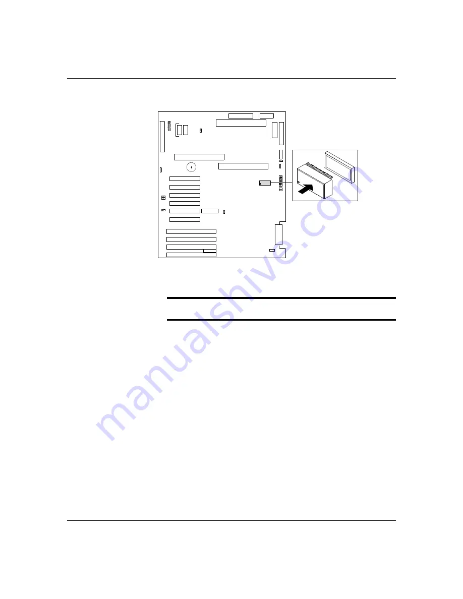
Figure 5-10. Non-Volatile Memory Location
Rep l aci n g t h e No n - V o l at i l e M emo ry
Notice: Observe static precautions. Use an antistatic
wrist strap.
1. Power off the system and remove the top cover as
described earlier in this chapter.
2. If the non-volatile memory is secured by a tie-wrap,
remove the tie-wrap. Using an IC removal tool or a
small pointed tool, gently pry up each end of the
non-volatile memory and pull it straight up out of its
socket (Figure 5-10).
3. Position the new chip over its socket so the dot is
properly oriented. Carefully insert the chip into its
socket connectors.
4. Press down on the chip until it is firmly seated in its
socket.
5. Replace the top cover and turn on the system.
6. Run the BIOS SETUP and SCU to restore proper
configuration settings.
Summary of Contents for HX4000
Page 1: ... Server HX4000 U s e r s G u i d e ...
Page 6: ...raham ...
Page 8: ...Bill Graham ...
Page 9: ...Chapter 1 Introduction Contents Organization 1 Notational Conventions 3 ...
Page 10: ...Bill Graham ...
Page 14: ...1 4 Introduction ...
Page 16: ...x ...
Page 44: ...2 28 Features ...
Page 46: ...x ...
Page 53: ...3 7 Setup ...
Page 55: ...1231231 Billy Graham ...
Page 82: ...4 27 Configuring Your System Figure 4 3 System Board Jumpers ...
Page 146: ...5 57 Upgrades and Options Figure 5 28 Removing the Rear Fan modules ...
Page 148: ...dfgdfg ...
Page 176: ...6 28 Problem Solving ...
Page 178: ...Bill GrahamBill Graham ...
Page 184: ...A 6 System Cabling ...
Page 185: ...Appendix B Memory Configurations Contents Memory DIMM Configurations 1 ...
Page 186: ...Bill Grahamaerrterterter ...
Page 190: ...B 4 Memory Configurations x ...
Page 191: ...Appendix C Option Boards Contents Introduction C 1 ...
Page 193: ...Appendix D Devices Contents Introduction 1 ...
Page 195: ...Appendix E Network Operating Systems Contents Introduction 1 ...
Page 198: ...rtyrtyrtyrtyry ...
Page 208: ...8 Glossary ...
Page 209: ......
Page 210: ... 904167 ...


