Setting Up the System 2-11
Rear View
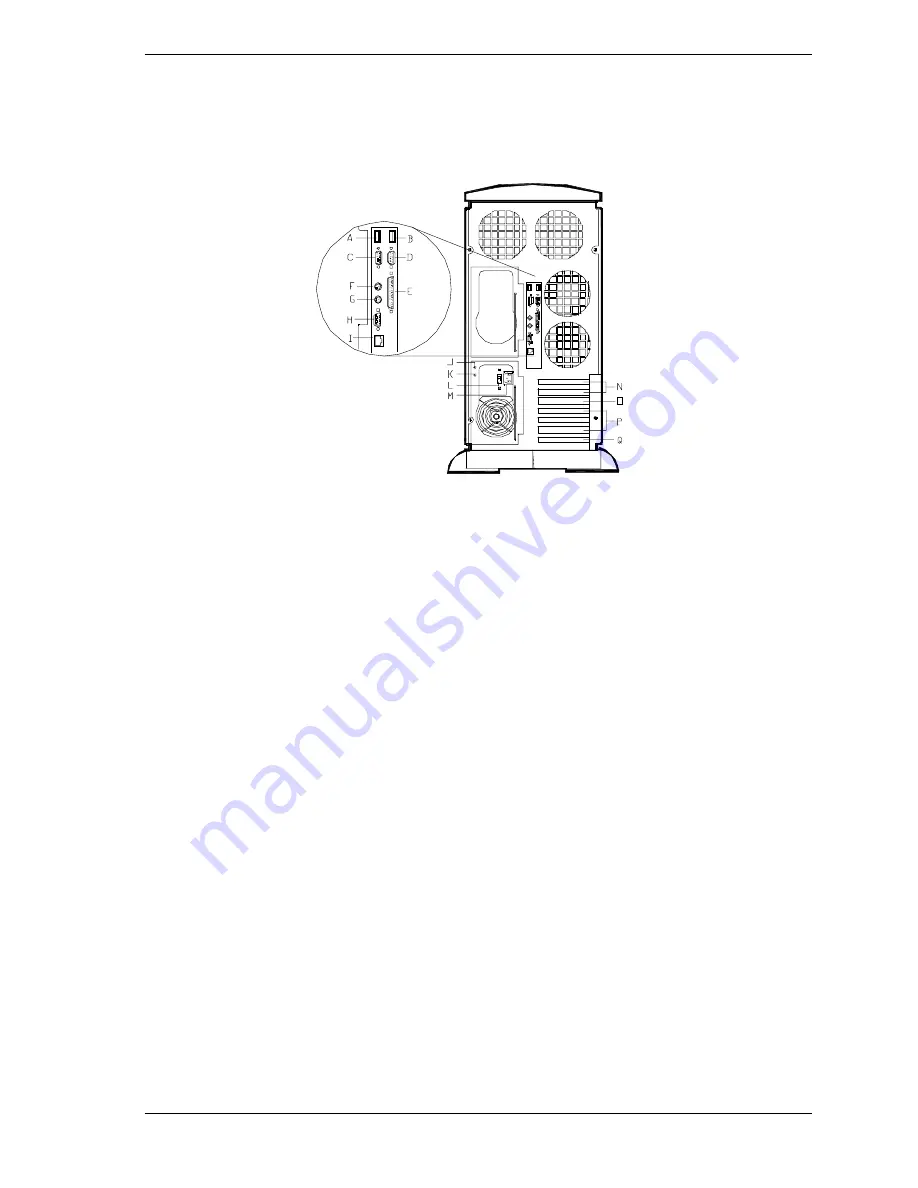
This figure shows the location of the following rear system features and
controls.
A
– USB2 connector
Second USB connector (black)
B
– USB1 connector
First USB connector (black)
C
– COM2 port
COM2 serial port 9-pin connector (turquoise)
D
– COM1 port
COM1 serial port 9-pin connector (turquoise)
E
– Printer port
Parallel port 25-pin connector (burgundy)
F
– Keyboard port
PS/2-compatible 6-pin mini-DIN connector (purple)
G
– Mouse port
PS/2-compatible 6-pin mini-DIN connector .(green)
H
– SVGA connector
SVGA monitor 15-pin connector (blue)
I
– LAN connector
RJ-45 Ethernet connector.
J
– DC Power fault
(amber light)
See Table "Power Supply Status Indicator LEDs (Rear Panel)"
that follows
K
– Power supply status
(green light)
See Table "Power Supply Status Indicator LEDs (Rear Panel)"
that follows
L
– Line voltage selector switch
Selects AC input power of 115 VAC or 230 VAC.
M
– AC input power connector
Supplies AC power to the power supply.
N
– 64 bit, 66 MHz PCI slots
Two PCI-66 MHz/64 bit add-in board slot locations.
O
– 64 bit, 33 MHz PCI slot
One PCI-33 MHz/64 bit add-in board slot location.
P
– 32 bit, 33 MHz PCI slots
Three PCI-33MHz/32 bit add-in board slot locations.
Q
– Combo PCI/ISA slot
One shared PCI or ISA add-in board slot location.
Rear Features and Controls
Summary of Contents for Express5800/120Mc2 series
Page 1: ... U s e r s G u i d e EXPRESS5800 120Mc2 ...
Page 2: ...xxx ...
Page 3: ... U s e r s G u i d e EXPRESS5800 120Mc2 ...
Page 50: ...2 18 Setting Up the System ...
Page 106: ...4 34 Upgrading Your System Plugging in the AC Power Cords ...
Page 154: ...B 22 Management Workstation Application ...
Page 155: ...C System Status Hardware Support Information ...
Page 166: ...10 Glossary ...
Page 171: ...xx ...
Page 172: ... 456 01524 000 ...


