Section 2: PCB Installation and Startup
2-16
◆
Section 2: PCB Installation and Startup
Aspire S Hardware Manual
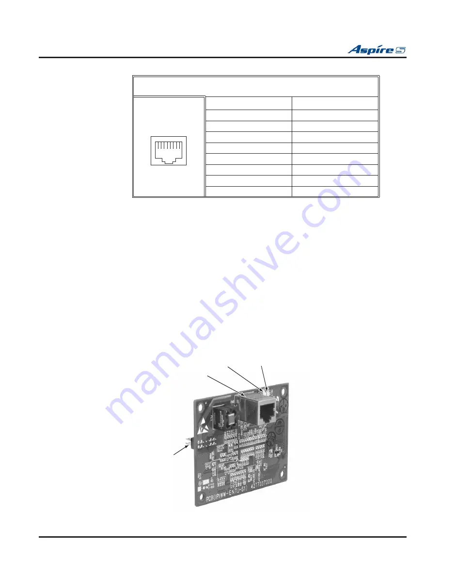
Connector Pin-Outs on ENTU
Installing the ENTU:
1.
Included with the ENTU is one plastic spacer. Install the spacer in the corner of the daughter board
which will not have a support provided by the CPU. Make sure to attach the spacer from the back of
the daughter board so when installed, the connectors are facing up.
2.
Position the ENTU PCB over the CN6 connector on the CPU. Push the board into the connector on
the CPU. Gently push the corner of the daughter board down so the spacer locks into the CPU.
To remove the daughter board, use pliers to squeeze the top of the spacer together, then gently
pull the daughter board off.
3.
Using the three screws provided with the ENTU PCB, secure the remaining three corners of the
PCB to the CPU.
Once the system has been powered up, with normal operation, the status LED will
fl
ash fast. If
trouble was found during the self diagnostics routine, the status LED will
fl
ash slowly.
4.
Using the ferrite core provided with the ENTU PCB, wrap the end of the ethernet cable which is
closest to the ENTU’s CN2 connector once around the ferrite core.
5.
Plug the ethernet cable into the CN2 connector.
6.
Refer to the
Aspire Software Manual (P/N 0893200)
or the VoIP Feature Supplement (P/N
0893204) for required VoIP programming.
Figure 2-6: ENTU INSTALLATION
Ethernet Cable Connector - CN2 (RJ45)
(10Base-T/100Base-TX Port)
Pin No.
Signal
1
Tx+
2
Tx-
3
Rx+
4
-
5
-
6
Rx-
7
-
8
-
12345678
089313
0-32
CN2 - RJ 45 Ethernet
Connector
CN3
CPU Connection
(For earth ground)
LD2 Link/Act LED
LD1 10/100 Port Status LED


