background image

Section 4: Telephones and Optional Equipment

4-54

Section 4: Telephones and Optional Equipment

Aspire S Hardware Manual

Installing the Power Failure Telephones:

1.

Connect an RJ-61 connector to the CN5 connector on the COIU PCB installed in the Aspire S.

2.

Install a modular jack for the single line telephone supporting PF operation. The modular jack 
should be within six feet of the phone.

3.

Run one-pair 24 AWG station cable from the cross-connect block to a modular jack.

4.

Terminate the extension leads to GRN/RED of the modular jack. Terminate the unused leads to the 
jack.

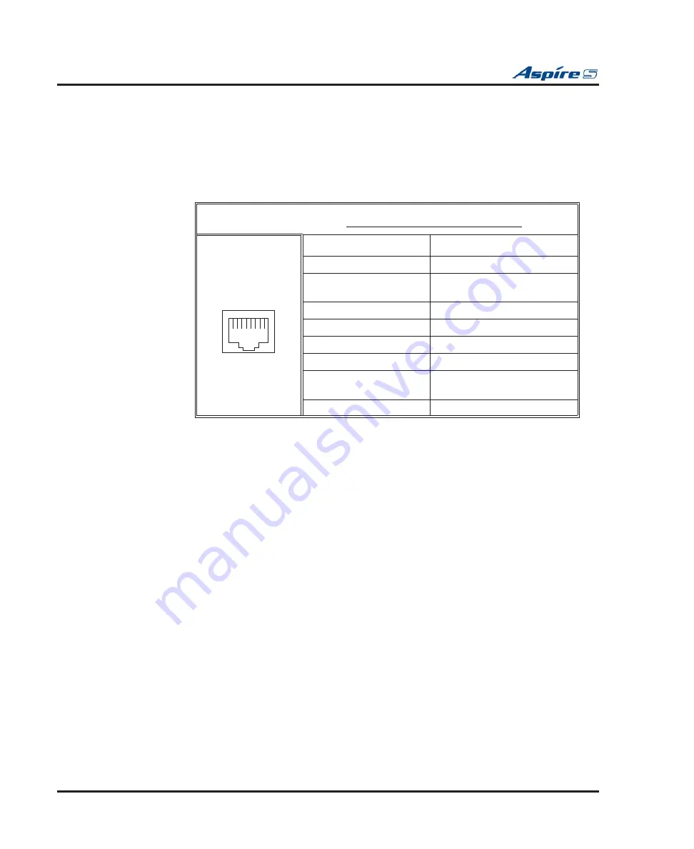
RJ61 Cable Connector - CN5

The CN5 connector is 

polarity sensitive (tip to tip, ring to ring)

Pin No.

Connection

1

-

2

SLT Interface

Power Failure Circuit - Tip

3

Circuit 2 - Tip

4

Circuit 1 - Ring

5

Circuit 1 - Tip

6

Circuit 2 - Ring

7

SLT Interface

Power Failure Circuit - Ring

8

-

12345678

Summary of Contents for Aspire S

Page 1: ... 1 Installing Cabinets 3 Installing Extensions and Trunks 4 Telephones and Optional Equipment 2 PCB Installation and Startup 6 LAN Connection Technical Support Web Site http ws1 necii com registration is required 7 Specifications and Parts ...

Page 2: ...Solutions Inc has no obligation to provide any updates or corrections to this manual Further NEC Unified Solutions Inc also reserves the right without prior notice to make changes in equipment design or components as it deems appropriate No representation is made that this manual is complete or accurate in all respects and NEC Unified Solutions Inc shall not be liable for any errors or omissions I...

Page 3: ...e Front Cover Figure 1 21 Figure 1 22 1 22 Section 2 PCB Installation and Startup 2 1 PCB LAYOUT 2 1 PCB Location 2 1 PCB INSTALLATION 2 2 Handling the PCBs 2 2 Installing an Extension or Trunk PCB Figure 2 2 2 2 To install an extension trunk PCB 2 2 Removing an Extension or Trunk PCB 2 4 To remove an extension trunk PCB 2 4 Uninstalling a PCB Slot Through Software 2 4 Where to Install the PCBs 2 ...

Page 4: ...BRIU S PCB 2 30 To install a BRI Interface PCB 2 31 Voice Mail IntraMail Figure 2 14 2 32 Installing an IntraMail Compact Flash Card 2 33 VoIP VOIPU S PCB Figure 2 15 2 34 LED Indications 2 35 Connector Pin Outs on VOIPU S PCB 2 36 Installing the VoIP PCB 2 37 Upgrading Your VOIPU S Firmware 2 38 VoIP VOIPDB S Daughter Board Figure 2 16 2 39 Installing an VOIPDB S Daughter Board 2 39 SYSTEM STARTU...

Page 5: ...abling 3 5 Installing a Cordless Telephone Figure 3 3 3 5 To install a cordless telephone 3 5 EXTENSION CUTDOWN SHEET 3 6 Extension Cutdown Sheet Configuration Figure 3 4 3 6 INSTALLING CO PBX LINES 3 8 Loop Start Line Cabling 3 8 Installing Loop Start Lines Figure 3 5 3 8 To install a loop start line 3 8 INSTALLING BRI TRUNKS 3 10 BRI Trunks Figure 3 6 3 10 Installing BRI Trunks 3 10 INSTALLING D...

Page 6: ... 4 16 4 20 Installing an External Recording System or External Ringer 4 20 Programming 4 21 HEADSETS 4 23 Connecting a Headset 4 23 IN LINE POWER ADAPTER ILPA R 4 24 Using the In Line Power Adapter Figure 4 17 4 24 Conditions 4 24 Installation 4 25 KEYSET LABELING 4 26 Labeling Your Phone Figure 4 18 4 26 Removing the Faceplate 4 26 Replacing the Faceplate 4 26 MUSIC SOURCES 4 27 Music on Hold Fig...

Page 7: ...e SLT Adapter 4 59 Telephones 4 60 34 Button Super Display Telephone P Ns 0890049 0890050 4 60 34 Button Display Telephone P Ns 0890045 0890046 4 61 22 Button Display Telephone P Ns 0890043 0890044 4 61 22 Button Standard Telephone P Ns 0890041 0890042 4 62 2 Button Telephone P Ns 0890047 0890048 4 62 Cordless Single Line Headset Telephone CT 11 P N 730090 4 63 Cordless Telephone P N 730088 730087...

Page 8: ...VoIP Telephone 6 5 Section 7 Specifications and Parts List 7 1 SYSTEM SPECIFICATIONS 7 1 Aspire S System Capacities 7 1 Aspire S PCB Capacities 7 2 Environmental Requirements 7 3 Environmental Specifications 7 3 Power Requirements 7 3 Site Requirements 7 3 Electrical Specifications 7 4 Aspire Soft Phone Requirements 7 5 CallAnalyst Requirements 7 6 IP Routers 7 7 Mechanical Specifications 7 8 2PGD...

Page 9: ...n 7 12 FCC DID Requirements 7 12 Cabling Requirements 7 13 Cable Requirements 7 13 Aspire S Configuration Guide 7 15 PARTS LIST 7 16 Station Equipment 7 16 Peripheral Station Equipment 7 17 Aspire Applications 7 18 Bluefire 7 18 Common Equipment 7 19 PCBs 7 19 Desi Labels 7 20 Spare Parts 7 22 ...

Page 10: ...Table of Contents viii Table of Contents Aspire S Hardware Manual For Your Notes ...

Page 11: ...ging equipment The cabinet should not be placed on unstable surfaces to avoid damage INSTALLING THE CABINET Unpacking Unpack the equipment and check it against your equipment lists The cabinet contains a power supply installed by the manufacturer however no PCBS are installed Inspect for physical damage If you are not sure about a component s function review the information for the component withi...

Page 12: ... cord packed outside the cabinet Environmental Requirements Meeting and maintaining established environmental standards maximizes the life of the system Be sure that the site selected for the cabinet is not 1 In direct sunlight or in hot cold or humid places 2 In dusty areas or in areas where sulfuric gases are produced 3 In places where shocks or vibrations are frequent or strong 4 In places wher...

Page 13: ...Section 1 Installing the Cabinet Aspire S Hardware Manual Section 1 Installing the Cabinet 1 3 1 Figure 1 1 REMOVING THE FRONT COVER Step 1 Step 2 0893130 1 screws screws Front Cover 0893130 2 1 2 ...

Page 14: ...nual Securing the Cabinet to the Floor Figure 1 2 Figure 1 4 1 Install the mounting brackets on the floor providing the appropriate spacing as shown below Figure 1 2 INSTALLING THE MOUNTING BRACKETS 08 93 13 0 22 Floor Front Wall surface Location of anchor bolts 9 1 2 8 12 12 11 1 2 16 7 16 ...

Page 15: ...abinet 1 5 1 2 Attach the floor mounting brackets to the cabinet Insert the tabs of the brackets into the slots on the bottom of the cabinet Figure 1 3 SECURE THE MOUNTING BRACKETS WITH SCREWS 0893130 20 Cabinet Bracket insertion hole Floor mount bracket Bracket insertion hole Tab Tab ...

Page 16: ...Manual 3 Secure the brackets to the cabinet with the screws provided with the bracket Then secure the mounting brackets to the floor using 4 6mm anchor bolts Figure 1 4 SECURE THE MOUNTING BRACKET WITH SCREWS 0893130 21 Screw 6mm Anchor Bolt 6mm Anchor Bolt Wall surface Screw Floor surface ...

Page 17: ... should protrude from the wall about 3 16 to allow the cabinet to slide over the screw heads It is suggested that plywood first be installed on the wall where the cabinet will be positioned This allows for secure anchoring of the screws which will be supporting the weight of the cabinet Figure 1 5 CABINET SPACE REQUIREMENTS 0893130 13 Floor surface Wall surface Ceiling Location of wood screws 13 3...

Page 18: ...Installing the Cabinet 1 8 Section 1 Installing the Cabinet Aspire S Hardware Manual Figure 1 6 INSTALLING THE WOOD SCREWS 0893130 14 Floor surface Wall surface A B C D Gap approx 3 16 Wall Wood screw Wood screw ...

Page 19: ...over the screws attached to the wall Making sure the cabinet moves down to the top of the keyhole opening Figure 1 7 PLACE THE CABINET ON THE WALL 3 Secure the cabinet to the wall by inserting the two screws into the bottom half of the cabinet Figure 1 8 FASTEN CABINET TO WALL 0893130 18 Floor surface Wall surface 0893130 19 Wall surface 2 wood screws ...

Page 20: ... the Cabinet Aspire S Hardware Manual Securing the Cabinet to a Rack Figure 1 9 Figure 1 12 1 Install the 19 rack mount bracket Figure 1 9 INSTALLING THE MOUNTING BRACKET ON THE RACK 0893100 44 19 inch Rack Screws attached to Rack Bracket 19 inch Rack Bracket ...

Page 21: ... 1 Installing the Cabinet Aspire S Hardware Manual Section 1 Installing the Cabinet 1 11 1 2 Remove the 2 screws from the front of the rack mount bracket Figure 1 10 REMOVE THE SCREWS FROM THE RACK 0893100 45 ...

Page 22: ...nual 3 Place the cabinet in the rack making sure the screw on the rack s mounting bracket catches the cab inet s molded stop on the bottom of the cabinet This will help secure the cabinet in place and pre vent it from sliding backwards Figure 1 11 INSTALLING THE CABINET IN THE RACK 0893130 11 ...

Page 23: ...talling the Cabinet Aspire S Hardware Manual Section 1 Installing the Cabinet 1 13 1 4 Replace the screws in the front of the rack which were removed in step 2 Figure 1 12 SECURING THE CABINET TO THE RACK 0893130 12 ...

Page 24: ... Hardware Manual INSTALLING THE PCBS PCB Installation Figure 1 13 Figure 1 16 1 Slide the PCB retaining bar back until you hear it click in place Do not loosen the screws Figure 1 13 MOVING THE RETAINING BAR 0893130 9 PCB Retaining Bar Push both ends when moving the retaining bar ...

Page 25: ...lling the Cabinet 1 15 1 2 Insert the PCB along the guide rails and firmly plug in the PCB connector to the CPU Figure 1 14 INSERTING THE PCB 0893130 10 Connector Guide rail top Guide rail bottom Connector in Cabinet SLOT3 thru SLOT 8 PCB Hold the corner of both ends of unit ...

Page 26: ...stalling the Cabinet 1 16 Section 1 Installing the Cabinet Aspire S Hardware Manual 3 Secure the PCB to the CPU by attaching the screw provided on the PCB as shown below Figure 1 15 SECURING THE PCB 0893130 5 Screw ...

Page 27: ...the Cabinet Aspire S Hardware Manual Section 1 Installing the Cabinet 1 17 1 4 Move the PCB retaining bar back in place to secure to top of the PCBs Figure 1 16 MOVING THE RETAINING BAR BACK 0893130 7 PCB PCB Retaining Bar ...

Page 28: ...vinyl chloride pipe 2 When installing a COIU or DIOPU PCB connect the grounding wire of the PCB to the PBXG ter minal plate and then run a grounding wiring from the PBXG terminal plate to a known earth ground using 14 AWG grounding wire The ETH and PBXG grounds should be separate they should not be combined 3 From the factory the FG is already connected to the AC power source No action is required...

Page 29: ... then be connected from the PBXG terminal plate to a known earth ground when these PCBs are installed in the system This grounding wire should be separate from the ETH grounding wire ETH Earth Ground This ground lug is used for lightning protection It should always be connected to the earth This grounding wire should be separate from the PBXG grounding wire FG Frame Ground This ground lug is conne...

Page 30: ...cable pass throughs one each on the left and right sides of the cabinet The block plate should be in place for any unused pass through in order to help keep dust out of the cabinet 1 There are two opening options one setting provides a small pass through the other provides a larger pass through Determine which type is required for the cabinet Figure 1 18 CABLE PASS THROUGH 0893130 15 Block Plate C...

Page 31: ...21 1 2 For the small pass through turn the block plate upside down and replace into the slot Figure 1 19 SMALL CABLE PASS THROUGH 3 For the large pass through remove the block plate and store it in the bottom right corner of the cabinet Figure 1 20 LARGE CABLE PASS THROUGH 0893130 16 0893130 17 ...

Page 32: ... the cover Figure 1 22 LOWER THE FRONT COVER 3 Tighten the four cover retaining screws A label is located on the right side of the cabinet which can be used to enter the date when the battery should be replaced In case of a power failure this battery provides back up of system data and RAM memory for approximately 30 months Program 90 11 01 can also be set to define an extension to receive an indi...

Page 33: ...stem with the default system settings To delete a PCB from the system power down the system and then remove the PCB from the sys tem cabinet Power the system back up and use Program 90 05 01 to delete the slot definition Whenever powering down the system check to make sure the only LED flashing on the CPU card itself in the lower left hand corner is the LD2 LED the LED located farthest right in th...

Page 34: ...rners All PCBs must be installed with the system power off Installing an Extension or Trunk PCB Figure 2 2 To install an extension trunk PCB Power down the system Whenever powering down the system check to make sure the only LED flashing on the CPU card itself is the LD2 LED farthest right of the LEDs This LED is located in the lower left hand corner of the CPU If any other LEDS are flashing on th...

Page 35: ...ely into position After installing all the PCBs the PCB retaining bar should be moved back into position and the screws for each of the PCBs should be tightened Figure 2 2 INSERTING PCBS 0893130 7 PCB PCB Retaining Bar 0893130 5 Screw 0893130 1 0 Connector Guide rail top Guide rail bottom Connector in Cabinet SLOT3 thru SLOT 8 PCB Hold the corner of both ends of unit ...

Page 36: ... on the cabinet Whenever powering down the system check to make sure the only LED flashing on the CPU card itself is the LD2 LED farthest right of the LEDs This LED is located in the lower left hand corner of the CPU If any other LEDS are flashing on the CPU wait until they stop or else the sys tem data may be corrupted All PCBs must be installed with the system power off Uninstalling a PCB Slot T...

Page 37: ...e gives you great flexibility when installing PCBs You can install a PCB in any slot provided you follow the guidelines in the chart below Item Description Max CPU MBU 32 Bit Central Processing Unit 1 DSPDB DSP Resource Daughter Board 1 installed on CPU ENTU S LAN CTI Ethernet Interface Board 1 installed on CPU 8ESIU S 8 Digital Stations 2 Can not be installed in slots 7 or 8 4SLIU S 4 Analog Stat...

Page 38: ...83 ch Digital Phase Locked Loop DPLL digital phase synchronization loop SFLM Generation DSP Digital Signal Processor provides C Channel control Tone Generation DTMF Tone Sender Receiver System Tone Sender MFC Tone Sender MF Signal Sender Sends caller information to CO for E911 Call Progress Tone Detector C Channel Control Time Switch control HDLC High Level Data Link Control Packet Proceessing Con...

Page 39: ...corrupt the flash or S RAM data If the flash memory becomes corrupted the system may not come up If the S RAM data is corrupted the telephones may have erratic operation When powering the system up or down wait 10 seconds before pressing the button again This allows the sys tem to complete the startup shutdown process 0893130 23 CN1 Serial Cable Connector D Sub 9 pin male Slots 3 8 CN4 DSPDB Conne...

Page 40: ...ring up the system without holding the SW1 switch The system boots loading software stored in flash memory SW3 3 1 Debugging Mode CN1 connector used for debugging Normal Mode CN1 connector used for serial interface SW4 3 1 Factory Use Used to initially load system software Normal Mode LED Indication Status RUN LD2 LED1 LED3 LED4 LED5 On Off Off Off On Steady with card installed System starting up ...

Page 41: ...eady with card installed SRAM error Blinking Off On On On Steady with card installed Flash memory booting start up error Blinking On On On On Steady with card installed Flash memory data error Blinking Blinking Blinking Blinking On Steady with card installed Read error of system program Blinking Off Off Off On Steady with card installed Running normally LED Indication Status RUN LD2 LED1 LED3 LED4...

Page 42: ...6 DSR 7 RTS 8 CTS 9 Digital Station RJ61 Cable Connector CN20 Pin No Connection 1 Ring for port 4 2 Ring for port 3 3 Ring for port 2 4 Tip for port 1 5 Ring for port 1 6 Tip for port 2 7 Tip for port 3 8 Tip for port 4 Digital Station RJ61 Cable Connectors CN21 Pin No Connection 1 Ring for port 8 2 Ring for port 7 3 Ring for port 6 4 Tip for port 5 5 Ring for port 5 6 Tip for port 6 7 Tip for por...

Page 43: ... connecting to a music source Note that Message Waiting lamping is not provided on the two analog ports on the CPU 4 Assign the purpose of the General Purpose Relay in Program 10 21 01 Analog Station RJ61 Cable Connector CN22 Pin No Connection 1 2 3 Ring for port 2 4 Tip for port 1 5 Ring for port 1 6 Tip for port 2 7 8 Polarity reversal feature available No Message Wait lamping External MOH BGM S...

Page 44: ...d installed the system will error and not boot up correctly 2 Push the power button on the cabinet to power down the system When powering the system up or down wait 10 seconds before pressing the button again This allows the system to complete the startup shutdown process 3 Once the system has powered down push in and hold the Load button 4 Press the power button to power the system back up 5 Cont...

Page 45: ...n this daughter board is installed on the CPU To install a DSPDB Daughter Board 1 Included with the DSPDB are four spacers Install one spacer in each corner of the daughter board Make sure to attach the spacers from the back of the daughter board so when installed the compact flash slot is facing up 2 Position the daughter board over the CN4 connector on the CPU Push the board into the connector o...

Page 46: ...allation and Startup Aspire S Hardware Manual To Upgrade the DSPDB Compact Flash Card 1 With the system power off remove the compact flash card from the DSPDB daughter board 2 Insert the new compact flash card Figure 2 5 REMOVING THE COMPACT FLASH CARD 0893100 90 ...

Page 47: ...power over ethernet is to be used to eliminate the separate power adapters a separate power source is required It is recommended that you use a power switch and or power hub which is IEEE 802 3AF com pliant For example the PowerDsine 6xxx series of products is unique in the fact that in addition to offering IEEE 802 3AF support it also provides for the NEC proprietary detection and therefore the I...

Page 48: ...ll the daughter board off 3 Using the three screws provided with the ENTU PCB secure the remaining three corners of the PCB to the CPU Once the system has been powered up with normal operation the status LED will flash fast If trouble was found during the self diagnostics routine the status LED will flash slowly 4 Using the ferrite core provided with the ENTU PCB wrap the end of the ethernet cable...

Page 49: ... status LED The CN3 and CN4 connectors each provide connection to 4 digital station ports The ESIU S requires one universal slot with a maximum of 2 PCB s per system Note that this PCB can not be installed in slot 7 or 8 The 8ESIU S consumes 8 ports ranging between ports 01 26 There must be enough available ports in order for the Aspire system to recognize an 8ESIU S PCB LED Indications LED Functi...

Page 50: ...4 Pin No Connection 1 Ring for port 4 2 Ring for port 3 3 Ring for port 2 4 Tip for port 1 5 Ring for port 1 6 Tip for port 2 7 Tip for port 3 8 Tip for port 4 RJ61 Cable Connector CN3 Pin No Connection 1 Ring for port 8 2 Ring for port 7 3 Ring for port 6 4 Tip for port 5 5 Ring for port 5 6 Tip for port 6 7 Tip for port 7 8 Tip for port 8 12345678 12345678 ...

Page 51: ...n and Startup 2 19 2 To install the ESIU PCB 1 Install the ESIU into a slot Note that this PCB can not be installed in slot 7 or 8 2 Tighten the screw on the PCB to secure the card to the cabinet Figure 2 7 ESIU INSTALLATION 0893130 29 CN6 CN7 CN4 CN3 LD2 PCB Status LED LD1 Live Status LED ...

Page 52: ...s installed in a universal slot with a maximum number of 4 PCBs per system This number of PCBs installed will reduce the number of 4SLIDB S PCBs which can be installed If 3 4SLIU S PCBs are installed only 1 4SLIDB S can be installed If 4SLIU S PCBs are installed the 4SLIDB S can not be used There must be enough available ports in order for the Aspire system to recognize an 4SLIU S PCB LED Indicati...

Page 53: ...the 4SLIDB S is to be used install this prior to inserting the 4SLIU S PCB into the cabinet 2 Install the 4SLIU S into the slot 3 Tighten the screw on the PCB to secure the card to the cabinet Figure 2 8 4SLIU S INSTALLATION 0893130 30 CN5 4SLIDB Connector LD1 PCB Status LED LD2 LD5 Line Status LEDs CN4 SLIDB PCB Earth Ground Connection CN3 ...

Page 54: ...on the 4SLIU S PCB Up to 2 PCBs can be installed in the system maximum but this number may be reduced depending on how many 4SLIU S PCBs are installed If 3 4SLIU S PCBs are installed only 1 4SLIDB S can be installed If 4SLIU S PCBs are installed the 4SLIDB S can not be used LED Indications Connector Pin Outs on 4SLIDB S LED Function LED Status Operation Status LD1 LD4 Indicates the status of termi...

Page 55: ...each corner of the PCB Make sure to attach the spacers on the front of the daughter board so when installed the com ponents are facing the 4SLIU S PCB 2 Position the 4SLIDB S s CN1 connector over the CN5 connector on the 4SLIU S PCB Press the boards together ensuring the plastic spacers lock in place 3 Install the 4SLIU S PCB into the slot Figure 2 10 8SLIDB S INSTALLATION 0 8 9 3 1 3 0 2 4 4SLIDB...

Page 56: ...nectors each provide connection to 2 analog trunk ports which are polarity sensitive tip to tip ring to ring The power failure circuit however is not polarity sensitive A maximum of 2 4COIUs per system is allowed LED Indications LED Function LED Status Operation Status LD5 PCB Status Indicates the status of the PCB Green On Initializing Green Flashing slow flash Initialization problem occurred dur...

Page 57: ...5 and CN7 connectors are polarity sensitive tip to tip ring to ring Pin No Connection 1 2 SLT Interface Power Failure Circuit Tip 3 Circuit 2 Tip 4 Circuit 1 Ring 5 Circuit 1 Tip 6 Circuit 2 Ring 7 SLT Interface Power Failure Circuit Ring 8 RJ61 Cable Connector CN7 Pin No Connection 1 2 3 Circuit 4 Tip 4 Circuit 3 Ring 5 Circuit 3 Tip 6 Circuit 4 Ring 7 8 12345678 12345678 ...

Page 58: ... slot The trunk ports are polarity sensitive tip to tip ring to ring Be sure the wiring is correct Once the system is powered up with normal operation the status LED will flash fast If trouble was found during the self diagnostics routine the status LED will flash slowly 2 Tighten the screw on the PCB to secure the card to the cabinet Figure 2 11 4COIU S INSTALLATION ...

Page 59: ...OPX trunk circuits 2 DID OPX trunk status LEDs 1 PCB status LED 1 PBXG Grounding Wire The CN201 connector provides connection to 2 analog DID trunk ports which are polarity sensitive tip to tip ring to ring The OPX circuits however are not polarity sensitive The DIOPU S requires one universal slot with 4 maximum PCBs per system The system will assign either trunk or extension ports to the PCB base...

Page 60: ...D will flash fast If trouble was found during the self diagnostics routine the status LED will flash slowly 3 Tighten the screw on the PCB to secure the card to the cabinet LED Function LED Status Operation Status LD1 PCB Status Indicates the status of the PCB Green On Initializing Green Flashing slow flash Initialization problem occurred during self check Green Flashing 100ms On Off Operating nor...

Page 61: ... SW100 SW200 Switches In the following cases the SW100 SW200 switches should be set to the ON position When the channel is assigned as a T Bus Point to Point With T Bus Point to Multipoint and if the system is connected at the end of the multipoint Otherwise the SW100 SW200 switches should be set to the OFF position Switch Name Switch Position Result Comments SW102 SW202 T T Bus Connection S S Bus...

Page 62: ...Green Flashing 100ms On Off Operating normally Green Off Downloading LD1 LD2 Indicates the Layer 1 link status of the lines Red On Layer 1 link established Red Off No link RJ61 Cable Connector CN2 T Bus Connection The CN2 connector is polarity sensitive tip to tip ring to ring Pin No Connection 1 2 3 TA 4 RA 5 RB 6 TB 7 8 T Bus Connection Pin Out for ISDN Cable at External DSU and Mod Jack Pin No ...

Page 63: ...ics routine the status LED will flash slow Once connected the ISDN Layer Link Status LEDs will be on steady when the Layer 1 link is established If there is no link the LED will be off 5 Connect the cable from the NT1 Network Termination cable to the CN2 connector on the BRI PCB 6 Tighten the screw on the PCB to secure the card to the cabinet Figure 2 13 BRI PCB INSTALLATION 0893130 28 CN102 Power...

Page 64: ... a plug in in skin full featured DSP based integrated Voice Mail with Automated Attendant for the Aspire S with software 2 50 or higher This card is installed on the DSP Resource daughter board The 8 port compact flash card provides 8 Voice Mail ports 8 hours of message storage and up to 160 mailboxes It requires a DSPDBU Daughter Board P N 0891003 The IntraMail Automated Attendant answers incomin...

Page 65: ...e back of the daughter board so when installed the compact flash slot is facing up 2 Position the daughter board over the CN4 connector on the CPU Push the board into the connector on the CPU Gently push the corners of the daughter board down so the spacers lock into the CPU To remove the daughter board use pliers to squeeze the top of the spacers together then gently pull the daughter board off 3...

Page 66: ...es 12 channels per system with the 4VOIPU with the 4VOIPDB S 24 channels are available Add the VoIP PCB after all other PCBs have been installed and the ports assigned Otherwise port number ing may be off as the VoIP PCB is recognized first even before the ports on the CPU This would mean the VoIP is assigned ports 1 4 and the digital and analog ports on the CPU would then follow When installing a...

Page 67: ...P PCB the system will still recognize the card and allow it to be used for IP phones Once a VoIP PCB has been installed in the system and trunks have been reserved for the PCB the only way to release the trunks for use by other PCBs is to remove the VoIP PCB and delete the slot using Program 90 05 For further details on using LAN devices refer to Section 6 LAN Connection page 6 1 LED Indications L...

Page 68: ...r Pin Outs on VOIPU S PCB RJ61 Cable Connector CN4 10Base T 100Base TX Port Pin No Connection 1 Tx 2 Tx 3 Rx 4 5 6 Rx 7 8 Serial Cable Connector CN2 Serial Cross Cable with Mini Din Used only for VOIPU S PCB maintenance Pin No Connection 1 DCD 2 RTS 3 RxD 4 GND 5 TxD 6 CTS 7 DTR 8 DSR 1 2 3 4 5 6 7 8 1 2 3 4 5 6 7 8 ...

Page 69: ...t 3 Set the run block switch UP Once the system is powered up with normal operation the status LED will flash fast If trouble was found during the self diagnostics routine the status LED will flash slowly 4 Connect the VOIPU S PCB to an external switching hub using an ethernet cable 5 Tighten the screw on the PCB to secure the card to the cabinet 6 Refer to the Aspire Software Manual P N 0893200 f...

Page 70: ...mware file VoIPU bin to the compact flash card 2 Power down the system 3 Connect a PC to the serial connector CN1 on the Aspire S using an RS232 cross cable 4 Open HyperTerminal on the PC The settings for the HyperTerminal session should be Baud Rate 38400 Data Bit 8 Non Parity Stop Bit 1 5 Set the SW3 switch on the Aspire S CPU to the 6 side 6 Insert the CF compact flash card into the VOIPU S PCB...

Page 71: ...orts can be set to 0 in Program 10 03 01 PCB Setup but the physical trunk ports are still assigned to the PCB and cannot be used for any other PCB unless the PCB is deleted from the slot in Program 90 05 Slot Control Refer to PCB Port Assignments on page 2 35 for details on the port usage with the VOIPDB S For further details on using LAN devices refer to Section 6 LAN Connection page 6 1 Installi...

Page 72: ...make sure you re starting with a defaulted system When powering up any other time simply press the power supply s AC power button Refer to Switch Settings and LED Indications on page 2 8 for CPU LED status 5 Wait about two minutes for the system to boot The telephone display at extension 301 will show the Time Date and extension number when the boot sequence completes Note Refer to TROUBLESHOOTING...

Page 73: ...s in order i e slot 3 first slot 4 next etc for a sequential number ing plan For example as the CPU provides 8 digital station ports ext 301 308 when 2 more station cards are installed in the following order the numbering plan below would apply Refer to PCB Port Assignments on page 2 35 for details on the port usage with the VOIPU S PCB and VOIPDB S As these cards are assigned trunk ports when ini...

Page 74: ...or complete details on programming Entering the Programming Mode Enter the system programming mode at extension 301 1 Press CALL1 You hear dial tone 2 Dial 3 Dial the system password 4 Press HOLD Port Defaults With the default settings the ports are assigned as follows Making Test Calls In the initial configuration All Programmable Function keys are line keys e g key 1 is line 1 All trunks are loo...

Page 75: ...tem recognizes the extension devices automatically when replacing the type of device connected the type must be undefined in Program 10 03 prior to connecting the new device For example if a port was previously used for a keyset and a DSS Console is to be installed in that same port it must first be undefined in Program 10 03 before the console is connected Handsfree Handset Page and BGM Volume Co...

Page 76: ...TA this directory would be overwritten if a second database were saved to the same card Each database to be saved will require its own separate card unless you choose to rename the directory after it is saved then rename it back to DATA when you need to access the database If the customer data needs to be reloaded the method for restoring the database is determined by how the database was saved Us...

Page 77: ...lication If the file was received by EMail detach the zip file to your computer 2 Locate the zip file on your computer and double click on the file The file opens the WinZip application and displays a list of the compressed files 3 Click ACTIONS EXTRACT or click the EXTRACT button on the tool bar 4 In the Extract window that appears make sure the USE FOLDER NAMES options is checked This is require...

Page 78: ...card slot CN5 on the CPU 4 Push in and hold the Load button 5 Turn the system power on by pressing the power button to power the system back up 6 Continue holding the Load button for approximately 10 seconds 7 Release the Load button 8 Wait until the Status LEDs on the CPU have the following indications approximately 2 minutes LD1 Flashing Red LD3 Flashing Red LD4 Flashing Red LD2 Steady Green 9 T...

Page 79: ...is flashing this LED is located farthest right of the LEDs If any other LEDs are flash ing wait until they stop before proceeding Turning off the power when other LEDs are flashing may corrupt the system data b Turn the system power off by pressing the power switch to OFF c Once the system has completed its powering down cycle all LEDs are off insert the Compact Flash card containing the software ...

Page 80: ... 11 07 45 01 and all the 47 xx programs and click to deselect Click START d Once that upload is complete under the SELECT RANGE drop down box select TELE PHONE DATA While holding down the CTRL key scroll to Program 16 02 and click to dese lect Click START e Once that upload is complete under the SELECT RANGE drop down box select VE DATA and click START A screen may appear indicating there is no da...

Page 81: ...ial port connector on the CPU Running program 90 13 03 in MAINTENANCE PROGRAMS prints a system PCB report Refer to Pro gram 90 13 03 System Information Output in the Software Manual The following is a typical report SYSTEM INFORMATION 011 03 03 09 49 slot location type assign port condition note 1 1 1 ESIU 1 8 Running Connect 2 1 2 SLIU 9 10 Running 3 1 3 ESIU 11 18 Running 4 1 4 SLIU 19 26 Runnin...

Page 82: ...Section 2 PCB Installation and Startup 2 50 Section 2 PCB Installation and Startup Aspire S Hardware Manual For Your Notes ...

Page 83: ...nks use the following pin information for the RJ 61 connector to connect your cables to the 66 blocks Important Install telephones as on premise extensions only Otherwise the telephones are highly susceptible to lightning strikes 66 Block RJ 61 Connector Block Termination 1 WHT BLU Pin 5 Block Termination 2 BLU WHT Pin 4 Block Termination 3 WHT ORN Pin 3 Block Termination 4 ORN WHT Pin 6 Block Ter...

Page 84: ...r extension port device groups Cross connect blocks provide an easy way to troubleshoot determine port identification numeri cally and determine port utilization Install cross connect blocks for the following interfaces All digital extension circuits CPU functions i e BGM MOH General Purpose Control Relay External page External alarms Data devices Installing Trunk Cross Connect Blocks It is also r...

Page 85: ... the extension B block for each extension 3 Connect the extension B block s 25 pair cable to the corresponding RJ 61 connector on the PCB 4 Install bridging clips on the extension B block Installing a Key Telephone Figure 3 1 1 Install a modular jack for each extension The modular jack should be within six feet of the phone 2 For each extension run one pair 24 AWG station cable from the cross conn...

Page 86: ...eir corresponding clips on the extension B block 3 Connect the extension B block s 25 pair cable to the corresponding RJ 61 connector on the PCB 4 Install bridging clips on the extension B block Installing a Single Line Telephone Figure 3 2 To install a single line telephone 1 Install a modular jack for each single line telephone The modular jack should be within six feet of the phone 2 For each e...

Page 87: ...lock Installing a Cordless Telephone Figure 3 3 To install a cordless telephone 1 Install a modular jack for each cordless tele phone The modular jack should be within six feet of the base unit 2 For each extension run one pair 24 AWG station cable from the cross connect block to a modular jack 3 Terminate the extension leads to GRN RED of the modular jack Important In some cases when testing the ...

Page 88: ...4SLIU S with the 4SLIDB S PCBs were installed in the cabinet in the order below the numbering plan would correspond as follows To determine extension assignments for the system cutdown the installer must identify the following in order Order of installation if additional PCBs installed after initially powering up Slot used PCB type 8ESIU S 4SLIU S 4SLIDB S Connector To determine where any group of...

Page 89: ... ORN BLK BLK GRN GRN BLK BLK BRN BRN BLK BLK SLT SLT BLK YEL BLU BLU YEL YEL ORN ORN YEL YEL GRN GRN YEL YEL BRN BRN YEL YEL SLT SLT YEL VIO BLU BLU VIO VIO ORN ORN VIO VIO GRN GRN VIO VIO BRN BRN VIO VIO SLT SLT VIO NOT USED RJ 61 Connector 1 Order Of Install Slot 8 ESIU 4 SLIU 4SLIDB DAUGHTER BRD 2BRIU 4VOIPU 4VOIPDB DAUGHTER BRD RJ 61 Connector 2 RJ 61 Connector 3 RJ 61 Connector 4 RJ 61 Connec...

Page 90: ... ports which are polarity sensitive tip to tip ring to ring The power failure circuits however are not polarity sensitive Installing Loop Start Lines Figure 3 5 To install a loop start line 1 Punch down one pair cross connect to the tip and ring leads for each line on the telco RJ21X CPE customer side of the block The CN2 and CN4 connectors are polarity sensitive tip to tip ring to ring 2 Punch do...

Page 91: ...al Section 3 Installing Extensions and Trunks 3 9 3 Figure 3 5 INSTALLING LOOP START LINES Bridging Clips 4 Loop Start Lines 4 Loop Start Lines One Pair Xconnect 4COUI 4COUI Line A Block Telco RJ21X 25 Pair Cable Loop Start Lines 1 4 Loop Start Lines 5 8 0893130 101 ...

Page 92: ... PCB Installing BRI Trunks 1 For each T Bus or S Bus line run cross connect wires between the pins on the cross connect block and the station block 2 Install bridging clips as required 3 From the cross connect block connect 2 pairs of wires For T Bus The opposite end is an 8 pin modular connector which is plugged into the NT1 Termi nation Connect a line cord from the NT1 Network Line Termination t...

Page 93: ...Trunks 3 11 3 Figure 3 6 BRI Interface T Bus Point to Point 0 8 9 3 1 3 0 1 0 2 Termination Termination NT1 Termination To Telco BRI Line Cross Connect Block Station Block Telco Mod Jack Line S Bus connection Not Currently Available T Bus connection RJ61 Jack RJ61 Jack ISDN Terminal ISDN Terminal BRI PCB ...

Page 94: ...d with a DIOPU PCB Installing DID Trunks 1 Punch down one pair cross connect to the tip and ring leads for each DID trunk on the CPE customer side of the RJ21X 2 Punch down the other end of the cross connect to the line A block tip and ring leads 3 Punch down a 25 pair cable to the opposite side of the line A block 4 Plug in the corresponding RJ 61 con nector to the DID PCB connector 5 Install bri...

Page 95: ...ween these two blocks DID Choke Installation 1 Remove the bridging clips on the A block and telco block for the DID lines 2 From the telco block solder the Tip lead to the 3 con nector on the choke 3 From the telco block take the Ring lead and solder it to the 1 connector on the choke 4 From the A block take the Tip 1 lead and solder it to the 4 connector on the choke 5 Solder the Ring 1 lead from...

Page 96: ... cabinet in the following order powering down between the PCB installation the following numbering plan would be in effect To determine trunk assignments for the system cutdown the installer must identify the following in order Order of installation Slot used PCB type 4COIU S 2BRIU S 2DIOPU S 4VOIPU S 4VOIPU S with 4VOIPDB S Amphenol connector To determine where any group of lines are installed no...

Page 97: ...LT RED BLK BLU BLU BLK BLK ORN ORN BLK BLK GRN GRN BLK BLK BRN BRN BLK BLK SLT SLT BLK YEL BLU BLU YEL YEL ORN ORN YEL YEL GRN GRN YEL YEL BRN BRN YEL YEL SLT SLT YEL VIO BLU BLU VIO VIO ORN ORN VIO VIO GRN GRN VIO VIO BRN BRN VIO VIO SLT SLT VIO NOT USED RJ 61 Connector 1 RJ 61 Connector 2 RJ 61 Connector 3 RJ 61 Connector 4 RJ 61 Connector 5 RJ 61 Connector 6 4 5 3 6 2 7 1 8 4 5 3 6 2 7 1 8 4 5 ...

Page 98: ...es between the main equipment and the telephone The telephone may need repair Yes No No Yes Yes If it still does not work replace the cable s and or connectors Connect another telephone to the same port on the ESIU Does it work The ESIU PCB may need repair If it still does not work replace the cable s and or connectors Yes No Check system programming for the extension Refer to the Aspire Software ...

Page 99: ...s for approximately 10 seconds then release them If the phone doesn t show TEST PUSH on the display then repeat Steps 1 3 and hold the keys down a few seconds longer 4 Press any key and its Logical Name should be displayed The following chart indicates the Logical Name for each key Quitting Test Mode 1 Lift the handset and then replace it 2 The phone returns to an idle condition Logical Name Table...

Page 100: ...iring between the cabinet and the analog telephone Connect the phone directly to the connector on the SLIU SLIDB Does it work Redo the wires between the main equipment and the telephone The telephone may need repair Yes No No Yes Yes No Yes No If it still does not work replace the cable s and or connectors Connect another telephone to the same port on the SLIU SLIDB Does it work The SLIU SLIDB PCB...

Page 101: ...s seated prop erly within the plastic circular well Check to make sure the small PCB that holds the mic holder in place is properly secured 1 Remove the four screws that hold the base plastic to the top panel and remove the base from the phone 2 Turn the phone so that the dial pad and keys are facing down 3 Locate the handsfree mic assembly in the lower left corner of the phone 4 Make sure the mic...

Page 102: ...e style has two black clips holding the small PCB in place over the mic assembly and it does not have a tie wrap as indicated in the picture below one should be added Install a small ordinary tie wrap as shown below to properly retain the mic holder and element in place 7 Re install the base to the phone and secure with 4 screws ...

Page 103: ...fore the connection to the system Is the wiring for the cables correct Redo the wires between the main equipment and the CO line The COIU PCB may need repair Yes Yes Yes No No No Yes No If it still does not work replace the cable s and or connectors Check system programming for the extension Refer to the Aspire Software Manual if necessary Try placing a call on the CO line Does it work Stop Yes No...

Page 104: ...er Setup for Analog Trunk Ports to make the trunk side tone the minimum for all analog trunks Usually an entry of 1 or 0 would have the best result but the final setting may vary for each trunk In Program 14 01 02 Basic Trunk Data Setup Transmit CODEC Gain Type and Program 14 01 03 Basic Trunk Data Setup Receive CODEC Gain Type change the default values for the analog trunk transmit and receive ga...

Page 105: ...nother BRIU PCB into the same slot in the CPU Does it work T Point portion of the external DSU may need repair The BRIU PCB may need repair Yes Yes No Yes No Yes No The main equipment cabinet CPU may need repair If it still does not work replace the cable s and or connectors Yes No Is the ISDN Layer1 link established LD2 LD3 flashing on the BRIU PCB No Redo the wires correctly No Request the CO pe...

Page 106: ...Section 3 Installing Extensions and Trunks 3 24 Section 3 Installing Extensions and Trunks Aspire S Hardware Manual For Your Notes ...

Page 107: ...ternal Ringer The system allows for a maximum of 10 2PGDAD modules to be installed 4 for ACI ports for external music source or recording system 2 for Door Boxes and 4 for Paging The 2PGDAD module also provides multi purpose controls These control relays can be used for controlling the external amplifier external music source and door lock control with the use of a Door Box The system allows for u...

Page 108: ...03 01 prior to connecting the line cord to the 2PGDAD Module 1 Remove the screw from the front of the 2PGDAD module Figure 4 2 REMOVE COVER FROM 2PGDAD MODULE 2 Using a screwdriver break out the plastic piece covering the cable hole Figure 4 3 REMOVE PLASTIC COVER FROM CABLE HOLE LED Indication Note LED 1 Green LED when CH1 in use Flashing green LED indicates dipswitch setting and programming for ...

Page 109: ...ire is exposed Channel 1 S3 S4 Function LED Indication Open Open Door Box On when in use Open Short External Paging Speaker On when in use Short Open External Ringer On when in use Short Short External Music on Hold Recording System On steady Channel 2 S5 S6 Function LED Indication Open Open Door Box On when in use Open Short External Paging Speaker On when in use Short Open External Ringer On whe...

Page 110: ...ction being connected for more detail on 2PGDAD connections Figure 4 5 CONNECTING CABLE TO THE 2PGDAD MODULE 6 Repeat Steps 4 and 5 for any additional connections required 7 Replace the cover and tighten the screw to hold the cover in place 8 If required for the function being used insert the RCA connectors into the CN2 Channel 1 and CN3 Channel 2 connectors on the back of the 2PGDAD module Figure...

Page 111: ...cord directly from an extension port on the Aspire Aspire S ESIU PCB or Aspire S CPU Though this is not the recommended connection it can be used to check if the extension has dial tone Should a direct connection of this type be made to the base station of the Cordless II or Cordless Lite II or to a 2PGDAD module the line cord must be 2 wire 1 pair If a 2 pair wire is used the system will provide ...

Page 112: ...S Hardware Manual 2 The back of the 2PGDAD module has two key hole type openings Place the 2PGDAD module over the two screws and slide it down or over depending on the positioning to lock it in place Figure 4 8 WALL MOUNTING THE 2PGDAD MODULE 0893100 60 Protruding screws 0893100 61 Protruding screws ...

Page 113: ...s it BGM plays whenever the user s extension is idle 1 Connect an RJ61 modular line cord from the CN23 connector on the CPU to the appropriate loca tion on the extension cross connect block 2 Connect the two conductor station cable from the cross connect block to the external music source 3 Install bridging clips as required Figure 4 9 CPU CONNECTIONS Refer to Background Music in the software manu...

Page 114: ...set correctly Refer to Figure 4 4 JUMPER SETTINGS on page 4 3 2 If a line cord was not previously connected to the 2PGDAD complete Steps 3 6 Otherwise skip to Step 7 3 Install a modular jack for each 2PGDAD module For each module run one pair 24 AWG station cable from the cross connect block to a modular jack Ground the unused pair 4 Terminate the extension leads to GRN RED of the modular jack Ter...

Page 115: ... THE 2PGDAD FOR A DOOR BOX 0893130 109 Door Box Connections S3 S6 Circuit type selection Relay 5 Door Box 1 Relay 6 Door Box 2 Door Box CH1 Door Box CH2 To Digital Station Port RCA Jack for External Page External Ringer and External Music Source Note Both Door Boxes cannot use both relays in the same 2PGDAD To Unlock Device for Door Box 1 ...

Page 116: ...tion 4 Telephones and Optional Equipment Aspire S Hardware Manual Figure 4 11 INSTALLING A DOOR BOX To Door Chime Box 1 Rear view To Door Unlock Device Misc Block Holes for mounting screws Screw Cross Connect to 66M1 50 Block to PGDAD Adaptor 0893130 108 ...

Page 117: ...um of 4 110 Button DSS Consoles As the 24 Button DLS Console is connected to the bottom of the phone an extension can only have one 24 button DLS Console installed An extension can have either a 24 Button DLS Console and 4 110 Button DSS Consoles installed assigned By default the 24 Button DLS Console has no keys defined These keys can be programmed as line keys extension DSS keys or programmable ...

Page 118: ...Consoles assigned 10 03 01 PCB Setup The system automatically assigns the terminal type 10 for the port which has a DSS console installed When installing a DSS the system must auto detect the console in order for the LEDS to function correctly When connecting the DSS to a extension previously defined with another circuit type undefine the circuit type enter 00 in Program 10 03 for the extension nu...

Page 119: ...overing the connector If a second adapter is required at a later time the console connection will need to be moved to the left in order to accommodate the cable 3 Plug the 24 Button DLS Console into the connector on the bottom of the keyset 4 Push the cable from the console into the cable channel to allow the phone to rest flat 5 Install the connector plate provided with the 24 Button DLS Console ...

Page 120: ...ect the USB interface of the NEC VSR unit to an available USB port on your PC 3 Unplug the line cord from your telephone and connect it to either port on the Dterm VSR unit 4 Connect the NEC telephone system to the remaining port on the Dterm VSR unit You are now ready to record For Windows 2000 or XP 1 Using the USB cable provided connect the USB interface on the Dterm VSR unit to your PC Windows...

Page 121: ...Section 4 Telephones and Optional Equipment Aspire S Hardware Manual Section 4 Telephones and Optional Equipment 4 15 4 2 Insert the NEC Installation CD in your CD drive and press Next ...

Page 122: ... been fully tested but has not yet been submitted to Microsoft for approval Press Continue Anyway 5 Press Finish to close the dialog box 6 Run Setup exe on your NEC Installation CD to install the Dterm Voice Security Recorder application software on your PC 7 Using the USB cable provided connect the USB interface of the NEC VSR unit to an available USB port on your PC 8 Unplug the line cord from y...

Page 123: ...rogram settings as required directory for storing messages message deletion file format etc It is recommended that after the initial installation of the Dterm Voice Security Recorder application that the audio balance of the remote side be changed to approximately 100 1 Open the Dterm Voice Security Recorder application 2 Click the Options tab 3 Using the up arrow button change the Remote Boost se...

Page 124: ...or External Paging cannot also be used for an analog Door Box Installing an External Page System 1 Connecting to the 2PGDAD Module Make sure the jumper in the 2PGDAD module for the channel is set correctly Refer to Figure 4 4 JUMPER SETTINGS on page 4 3 2 If a line cord was not previously connected to the 2PGDAD complete Steps 3 6 Otherwise skip to Step 7 3 Install a modular jack for each 2PGDAD m...

Page 125: ...rovides amplifiers for each page output port for a maximum of 8 dBM 600 ohms at 1KHz No additional page amplification is provided by the 2PGDAD module and if required an external page amplifier can be used for additional amplification 0893100 78 PGDAD Module External Relay Page Control Paging Amplifier Mute Circuit External Page To ESIU PCB CN2 or CN3 CN1 CN2 CN3 Relay 6 Relay 5 ...

Page 126: ...ACI analog port extension number the associated PGDAD relay closes and activates the ringer You could use this capability to control an emergency buzzer for a noisy machine shop floor for example In addition if programmed for ringing an incoming trunk call can activate the ringer buzzer Installing an External Recording System or External Ringer 1 Connecting to the 2PGDAD Module Make sure the jumpe...

Page 127: ...t back in order to reset the circuit types 10 05 01 General Purpose Relay Setup Define which relay circuits 5 8 on the 2PGDAD Module are used for General Purpose Relays 11 06 01 ACI Extension Numbering Assign extension numbers to ACI software ports Select a number outside of the normal extension number range Aspire S ACI Ports 1 8 Aspire ACI Ports 1 96 11 08 01 ACI Group Pilot Number Assign pilot ...

Page 128: ...on for Trunks ACI Automatic Recording for Incoming Call Determine whether a trunk should be automatically recorded when an incoming call is received 0 off 1 on 14 09 04 ACI Conversation Recording Destination for Trunks ACI Automatic Recording for Outgoing Call Determine whether a trunk should be automatically recorded when an outgoing call is initiated 0 off 1 on 15 07 01 Programmable Function Key...

Page 129: ...vail able from handsfree The headset plugs into a separate jack on the bottom of the phone This allows the use of the handset or headset whichever is convenient at the time Simply connect the headset into the headset jack located on the bottom of the keyset This jack is located right next to the handset jack so make sure to connect to the proper jack Examples of compatible headsets are the NEC Pol...

Page 130: ...l outlet using the AC R Adapter P N 780135 NEC power supply PoE managed switch BlueFire 200 24 in line and spare pair detection Cisco Data Switch CDP supported in line and spare pair detection In Line Power Adapter Conditions Only IP telephones supported by center feed can be used This adapter can not be used with the H 323 telephones When center feed is used first unplug the adapter from the ethe...

Page 131: ...s than 328 feet The adapter can be positioned either closer to the keyset or switch it does not matter 4 Connect a cross over LAN cable to the LAN connector on the ILPA R adapter Plug the opposite end into the switch which is to provide power to the telephone If a straight through cable is used NIC Auto Detection must be enabled in Programs 10 12 05 NTCPU or 84 05 02 VOIPU Figure 4 17 NEC TERMINAL...

Page 132: ...2 x 11 paper which allows for easy printing by any printer dot matrix laser etc Removing the Faceplate 1 At the lower right hand corner of the telephone you ll notice a small notch in the faceplate plastic Use this notch to help lift the faceplate up Each corner has a plastic locking pin which releases as the faceplate is lifted up If the faceplate is dropped these pins may pop out of place Be car...

Page 133: ...e MOH source e g a tape deck to run only when a call is placed on Hold The maximum applied voltage for the relay is 24vDC at 5A the relays are normally open and close when a call is put on hold Installing External Music on Hold 1 Connecting to the CPU Connect an RJ61 modular line cord from the CN23 connector on the CPU to the appropriate loca tion on the extension cross connect block 2 Connect the...

Page 134: ... CN1 connector on the 2PGDAD module 7 Connect an RCA jack to the audio output s on the back of the 2PGDAD module 8 The opposite end of this cable is connected to the external music source either directly or by con necting to the cross connect block where the music source is connected Figure 4 19 CPRU CONNECTIONS Figure 4 20 2PGDAD CONNECTIONS 0893130 106 Music Input Music Relays CPU PCB CN23 Cross...

Page 135: ...R Analog Port Adapter with Ringer CTA Serial Interface RS 232C CTU USB Interface HF R Speakerphone Adapter PSA Aspire IPhone Power Failure IP VoIP Connection 24 Button DLS Console refer to page 4 11 for complete details on connecting the DLS The following chart indicates if there are restric tions when combining certain adapters Select the adapter in the column and then select the adapter in the r...

Page 136: ...ak 3 Remove the cover Figure 4 22 REMOVE THE ADAPTER COVER 1 The IP Adapter takes the full space provided for adapters on the keysets Therefore if an IP adapter is installed no other adapters can be used 2 Only one adapter of the same type can be used on a keyset 3 As there is only one voice path provided for adapters the APR and APA adapters can not both be used on the same keyset 4 Due to protoc...

Page 137: ...tion is not possible Feature Hardware CPU Built In Serial Port ENTU S Ethernet Port CTA Adapter CTU Adapter PCPro Yes Yes No No WebPro for installer Yes Yes No No WebPro for user No Yes No No SMDR Output to Printer Yes No Yes Yes SMDR Output to PC Yes Yes Yes Yes Hotel Motel Data Output No No Yes Yes Traffic Report Yes No Yes Yes System Information Printout Yes No Yes Yes Alarm Information Printou...

Page 138: ...a flat head screwdriver remove the plastic punch out piece covering the connector 3 Set the dip switches on the ADA adapter to the required position The SW1 and SW2 switches should be set to 1 for either application CAUTION Be sure the connected audio device provides a standard AUX level input The use of monitoring recording or listening devices to eavesdrop monitor retrieve or record telephone co...

Page 139: ... ribs in too much or they may break Figure 4 25 REMOVE THE SCREW FROM THE ADA ADAPTER 5 Determine which terminals should be connected Terminals T3 and T4 are used for wiring to a recorder T6 and T7 are used to activate a relay T his relay will turn on a recorder when a call is placed ore received The dip switch 1 must be set to the on position 6 Run the cable to the ADA adapter through the opening...

Page 140: ...nector into place The top latch on the top of the adapter should lock into place when it is properly positioned 13 In order for the ADA adapter to recognized correctly before plugging in the keyset make sure that in Program 10 03 01 the extension number to be used for the ADA adapter is undefined 14 Plug the line cord back into the keyset To avoid any hardware problems when removing the adapter fi...

Page 141: ... connector 3 Set the dip switches on the ADA2 adapter to the required position The SW1 switch should be set to 2 and the SW2 switch should be set to 1 The SW1 indicates the type of adapter 2 ADA2 and the SW2 switch sets the impedance 1 620 Ohms 2 30 Ohms The SW2 switch should remain in the 1 position CAUTION Be sure the connected audio device provides a standard AUX level input The use of monitori...

Page 142: ...bs in too much or they may break Figure 4 33 REMOVE THE SCREW FROM THE ADA2 ADAPTER 5 Determine which terminals should be connected Terminals T3 and T4 are used for wiring to a recorder T6 and T7 are used to activate a relay T his relay will turn on a recorder when a call is placed ore received The dip switch 1 must be set to the on position 6 Run the cable to the ADA2 adapter through the opening ...

Page 143: ...prongs into the bottom of the phone 12 Push the connector into place The top latch on the top of the adapter should lock into place when it is properly positioned 13 Plug the LAN cable and AC adapter cable into the keyset To avoid any hardware problems when removing the adapter first unplug the line cord then the power cord then any other adapter cables 08 93 10 0 70 T6 T7 ADA Module Line in CN2 T...

Page 144: ... there is only one physical port number assigned to the phone If both the analog device and keyset are picked up at the same time the analog device takes priority If the keyset is on a call and the single line telephone is picked up the single line telephone will take the call from the keyset When installing the APR adapter there must be an extension port available for the adapter or it will funct...

Page 145: ...y wish to remove the wall mount bracket to allow for easier adapter installation Figure 4 40 POSITIONING THE ADAPTER 6 Hook the two plastic prongs into the bottom of the phone 7 Push the connector into place The top latch on the top of the adapter should lock into place when it is properly positioned 8 In order for the APD APR adapter to recognized correctly before plugging in the keyset make sure...

Page 146: ...set to which it is attached like an APA remove the terminal type in this option With this setup when the analog device is in use it busies out the keyset as there is no separate port number assigned for the adapter To reverse this and allow the APR to have its own extension number simply reassign the terminal type 12 in this option 10 03 07 PCB Setup The port number of the APR Adapter is displayed...

Page 147: ...keyset should first be unplugged from the system Telephones with any adapters installed cannot be wall mounted The bracket will not accommodate the adapter s Installing the CTA Adapter Be sure to follow these steps in order to allow the system to properly recognize the CTA Adapter 1 Unplug the line cord from the keyset 2 If only one adapter is to be installed on the phone the adapter should be ins...

Page 148: ...ws1 necii com 16 Connect the serial cable from the PC to the CTA Adapter System Programming SMDR Program 14 01 06 Basic Trunk Data Setup SMDR Print Out Use this option to have the system include exclude the trunk you are programming form the SMDR printout See Program 35 01 and 35 02 for SMDR printout options 0 No print out 1 Prints out Program 15 02 19 Multi LineTelephone Basic Data Setup CTA Data...

Page 149: ...s the output for system information report 0 no setting 1 NTCPU COM port 2 NTCPU USB port 4 CTA CTU adapter Set the baud rate for the COM port in Program 10 21 02 The system can have up to 50 reports Program 90 13 02 System Information Output Destination Extension Number If the output port type 90 13 01 is a CTA enter the extension number with the CTA connection For TAPI setup refer to the Aspire ...

Page 150: ...f the keyset on which the CTU adapter is to be connected was previously installed undefine the circuit type in Program 10 03 01 for the extension enter 0 as the circuit type 3 If only one adapter is to be installed on the phone the adapter should be installed on the right hand side of the phone beneath the handset Using a flat head screwdriver remove the plastic punch out piece covering the connec...

Page 151: ...gram 90 13 02 System Information Output Destination Extension Number If the output port type 90 13 01 is a CTU enter the extension number with the CTU connection For TAPI setup refer to the Aspire CTI Manual P N 0893102 for complete details 6 Install the CTU Adapter driver by double clicking on the SETUP EXE file During the installation of the driver select the non procedure mode by default the CT...

Page 152: ...n the power cord then any other adapter cables To print from the CTU to a printer you must connect the CTU to a PC with the printer then connected to the PC you can not have a direct CTU to printer connection 14 Confirm in Program 10 03 04 that the CTU adapter is recognized for the keyset s port 15 You can now confirm the port assignment using the Windows Device Manager click Start Set tings Contr...

Page 153: ...the following instances No power supplied to the keyset PSTN is selected using the LAN PSTN Change Switch on the adapter With this switch set to PSTN a call cannot be made using the LAN even if the LAN is function ing correctly and power is available If the initial software operation for the IP keyset has not yet been completed before the IP keyset is powered up When installing or removing the ada...

Page 154: ... by pickup up the handset If the switch is set to the LAN position answer the call by changing the switch to PSTN and then pickup up the handset If you receive a call via PSTN during a conversation via LAN answer the call by completing the LAN call and placing the handset back into the cradle Change the LAN PSTN Change Switch to PSTN and then lift the handset to answer the call If you change the L...

Page 155: ...t be installed on an Aspire 2 button phone or IPhone When installing or removing the adapters the keyset should first be unplugged from the system Telephones with any adapters installed cannot be wall mounted The bracket will not accommodate the adapter s Installing the HF R Adapter 1 Unplug the line cord from the keyset 2 If only one adapter is to be installed on the phone the adapter should be i...

Page 156: ... light as long as the microphone switch on the adapter is enabled The microphone s sound can be muted using the switch on the microphone The microphone cable provides 6 of cable The placement of the microphone unit can be anywhere within this 6 distance For the best voice quality it is recommended that the microphone unit be positioned with either the front or the side of the microphone facing the...

Page 157: ...he separate ethernet switch should be a 100Base full duplex switch To avoid network problems and to ensure good voice quality do not use a Repeater Hub 10Base When installing or removing the adapters the keyset should first be unplugged from the system Telephones with any adapters installed cannot be wall mounted The bracket will not accommodate the adapter s Installing the VoIP Adapter 1 Unplug t...

Page 158: ...upplied by the LAN 8 Plug in the LAN straight thru cable from the 4VOIPU S PCB LAN connector for the phone opera tion If needed connect the PC cross cable to the VoIP Adapter 9 Refer to the Aspire Software Manual P N 0893200 for required programming To avoid any hardware problems when removing the adapter first unplug the line cord then the power cord then any other adapter cables Figure 4 53 WIRI...

Page 159: ...The 4COIU S PCB provides 1 Power Failure Transfer circuit The CN5 connector provides connection to 4 analog trunk ports which are polarity sensitive tip to tip ring to ring The power failure circuits however are not polarity sensitive A maximum of 2 4COIU S PCBs per system is allowed Connector Pin Outs on COIU PCB for Power Failure Circuits RJ61 Cable Connector CN5 The CN5 and CN7 connectors are p...

Page 160: ...operation The modular jack should be within six feet of the phone 3 Run one pair 24 AWG station cable from the cross connect block to a modular jack 4 Terminate the extension leads to GRN RED of the modular jack Terminate the unused leads to the jack RJ61 Cable Connector CN5 The CN5 connector is polarity sensitive tip to tip ring to ring Pin No Connection 1 2 SLT Interface Power Failure Circuit Ti...

Page 161: ...phones and Optional Equipment Aspire S Hardware Manual Section 4 Telephones and Optional Equipment 4 55 4 Figure 4 54 POWER FAILURE CIRCUIT INSTALLATION 0893130 27 CN5 CN7 LD5 PCB Status LED LD1 LD4 Live Status LEDs ...

Page 162: ...rpose Relay service code 880 0 toggles the relay open or closed The service codes indicated are the default codes Refer to Program 11 12 50 to redefine the code as needed OR 1 Connecting to the 2PGDAD Module Make sure the jumper in the 2PGDAD module for the channel is set correctly Refer to Figure 4 4 JUMPER SETTINGS on page 4 3 2 If a line cord was not previously connected to the 2PGDAD complete ...

Page 163: ... when the Door Box contact is activated using the FLASH key or when the external page zone is called The maximum applied voltage is 24vDC at 5A for each contact Figure 4 55 2PGDAD PAGE CONNECTIONS 0893100 78 PGDAD Module External Relay Page Control Paging Amplifier Mute Circuit External Page To ESIU PCB CN2 or CN3 CN1 CN2 CN3 Relay 6 Relay 5 ...

Page 164: ...ation cable for each SLT Adapter to a cross connect block 2 Run one pair cross con nect from the cross con nect block to the extension B block for each SLT Adapter 3 Connect the extension B block s 25 pair cable to the corresponding RJ 61 connector on the ESIU PCB 4 Install bridging clips on the extension B block 5 Install a modular jack for the SLT Adapter within six feet of the module s location...

Page 165: ...s from the front of the SLT Adapter 3 Lift the cover off the adapter 4 Using the two screws provided with the SLT Adapter attach the back cover to the desired location 5 Replace the front cover and the two screws removed in Step 2 6 Plug the two modular line cords back into the SLT Adapter which were removed in Step 1 0893100 65 Figure 4 57 REMOVING THE COVER 0893100 64 Tighten two screws Figure 4...

Page 166: ...rd The telephone s 24 programmable function keys can be cus tomized by the user for one button access to co workers fea tures like Paging or Park or specific outside lines The Dual LEDs in each programmable key help the user see which calls are for them and which features are active Access to other commonly used features is sim plified by 15 fixed feature keys In addition the Super Display Telepho...

Page 167: ...Display Telephone P Ns 0890043 0890044 The 22 Button Display Telephone features a 3 line 24 char acter display with 4 interactive soft keys for intuitive feature access in addition to 12 function keys with Dual LEDs The function keys are user programmable and can provide 1 but ton access to co workers features and outside lines The tele phone additionally provides 10 user programmable One Touch Pe...

Page 168: ...ntercom calls without touching the phone The 11 fixed feature keys provide quick access to many essential features and the Message Waiting lamp always shows when there are unanswered messages At a glance 22 Button Telephone Part Numbers 0890041 0890042 Function Keys Accepts 110 Button DSS Accepts 24 Button DLS Handsfree Speakerphone Dual LEDs ADA Adapter ADA2 Adapter No APA Adapter APR Adapter CTA...

Page 169: ...p in mind that although there should not be a problem with interfer ence from WLAN s 802 11b and 802 11g both share the same frequency as the CT 11 telephone In theory the CT 11 is a narrow band high power device where as the 802 11b and 802 11g are both wide band low power technologies Therefore the higher power CT 11 could disrupt the low power device and slow the data network There are however ...

Page 170: ...nstead of the spread spectrum modulation Recommended Usage Guidelines for Cordless Phones In ideal conditions multiple spread spectrum type cordless phones Cordless II can be utilized in the same environment However due to the possible interference problems caused by the bases being placed in close proximity to each other we recommend the following Spread Spectrum Phones Cordless II P N 730088 Whe...

Page 171: ...the Cordless II 30 channels on the Cordless Lite II This will help avoid any problems with interference between handsets when going off hook Connecting the Telephone Line There are two types of phone outlets 1 Modular Jack Plug the telephone line cord from the base unit into a standard modular telephone jack 2 Hardwired Jack A modular jack converter not included is required You may need to rewire ...

Page 172: ... create a trip hazard or where it could become chafed and create a fire or other electrical hazard Note The AC adaptors furnished with this phone may be equipped with a polarized line plug a plug having one blade wider than the other This plug will fit into the power outlet only one way If you are unable to insert the plug fully into the outlet try reversing the plug Do not alter the shape of the ...

Page 173: ...he Base Unit on the posts of the wall plate and push down until it s firmly seated 7 Plug the AC Adapter into a standard 120V AC wall outlet Note Do not use an outlet controlled by a wall switch Figure 4 62 ATTACHING THE WALL MOUNT PLATE Figure 4 63 ATTACHING TO THE WALL PLATE Direct Wall Mounting If you do not have a standard wall plate you can mount your phone directly on a wall Before mounting ...

Page 174: ...charging unit consider the following Select a location away from electrical cables pipes or other items behind the mounting location that could cause a hazard when inserting screws into the wall Make sure the wall material is capable of supporting the weight of the Desktop Charger Use 10 screws with anchoring devices suitable for the wall material where the Desktop Charger will be placed 1 Insert ...

Page 175: ...tions With the Cordless II phone make sure to place the bat tery in the handset so the negative is on the left and positive is on the right the metal contacts should face down toward the phone With the Cordless Lite II phones the battery pack cable must be plugged into the handset 3 Securely close the battery compartment cover by sliding it up until it snaps into place Figure 4 70 INSTALLING THE B...

Page 176: ...h back slightly to remove the battery if it is needed Otherwise leave the battery in the Charging Compartment It will not overcharge Low Battery Indicator When the battery in the handset is low and needs to be charged you will see a LOW warning icon on the display While in standby mode the phone will beep every 15 seconds for three minutes In talk mode the tone will beep every 3 seconds as long as...

Page 177: ...ur desk and when you need to be away from your desk you can carry the cordless phone with you Refer to Installing a Cordless Telephone Fig ure 3 3 page 3 5 for details on connecting the phones Headset The optional headset provides a handsfree option for your convenience With the headset installed you can use the belt clip to carry the handset and conduct a conversation using the headset To install...

Page 178: ...rupted frequently Make sure that the base unit s antenna is fully vertical Move closer to the base unit Warning tone and NO SERVICE message Move closer to the base unit Handset doesn t ring The battery pack may be weak Charge the battery for 5 6 hours Make sure the base unit antenna is fully vertical The handset may be too far away from the base unit Ensure the Ringer ON OFF switch is in the ON po...

Page 179: ...able legs which allow each phone to be angled at a height which best suits the user At a glance H 323 IP Phone P N 780005 This UIP300 H 323 IP phone is a business IP phone in enterprise LAN environment and will be connected to IP PBX systems via RJ45 network cable Standard Telephone Features Alphanumeric LCD display with 2 lines of 24 characters 10 LED indicators Line 1 Line 21 Status Mute Speaker...

Page 180: ...vity Detection VAD QoS IEEE 802 1 p q Based and DiffServ Jitter Compensation 10 100 Base T Ethernet Interface When installing an Aspire IP phone IPhone Aspire keyset with IP adapter or H 323 phone an AC DC adapter is required for local power or for central power one of the following must be used 24 Port Power PoE Managed Switch BF200 24 NEC standard product 12 Port Power Supply Patch Panel SN1604 ...

Page 181: ...PIRE IPHONE DIP SWITCHES 2 Plug an AC DC adapter into the AC jack on the adapter if power is not supplied by the LAN 3 Plug in the LAN straight thru cable from the 4VOIPU S PCB LAN connector for the phone opera tion If needed connect the PC cross cable to the VoIP Adapter 4 Refer to Section 6 LAN Connection page 6 1 for additional LAN and PoE information 5 Refer to the Aspire Software Manual P N 0...

Page 182: ...splay up from the top of the phone 2 You ll hear a click when it locks into the first position If you wish the display to be at a higher angle continue to lift the LCD display until a second click is heard This is the highest angle avail able for the display Figure 4 76 LIFTING THE LCD DISPLAY Lowering the LCD 1 On the base of the phone beneath the display gently pull the lever out This allows the...

Page 183: ... the phone to set the leg into position 3 To set to the third position starting when set at the first position Fold the leg down and slightly pull the extension out Tip the extension down then slide it back until the slide reaches the opposite end of the extension Pull the leg forward and then push the completely extended leg back into the phone to set it into position To set to the third position...

Page 184: ...ones and Optional Equipment 4 78 Section 4 Telephones and Optional Equipment Aspire S Hardware Manual Figure 4 79 SETTING THE LEGS POSITION 2 Figure 4 80 EXPANDING THE LEG HEIGHT POSITION 3 0893100 118 0893100 119 1 2 ...

Page 185: ...ones and Optional Equipment Aspire S Hardware Manual Section 4 Telephones and Optional Equipment 4 79 4 Figure 4 81 EXTENDING THE LEGS POSITION 3 Figure 4 82 SETTING THE LEG POSITION POSITION 3 0893100 120 0893100 121 ...

Page 186: ...pter s There are two types of mounting brackets one for the multi line keysets and one for the 2 button telephone Installing the Wall Mount Handset Bracket Figure 4 83 Figure 4 89 1 Remove the integrated wall bracket from the bottom of the phone Refer to Figure 4 83 From the center cut out pull the bracket up and out 2 Remove the wall mount hookswitch tab located on the bracket by gently pulling t...

Page 187: ...nes and Optional Equipment Aspire S Hardware Manual Section 4 Telephones and Optional Equipment 4 81 4 Figure 4 84 REMOVING THE HOOKSWITCH HANGER Figure 4 85 INSTALLING THE HOOKSWITCH HANGER 0893100 115 2 1 0893100 114 ...

Page 188: ...e 4 83 attach the wall bracket to the wall using three screws in the positions indicated below to the desired wall location Figure 4 86 ATTACHING THE BRACKET 5 Attach the phone to the wall mount bracket by inserting the bottom hooks indicated by A in Fig ure 4 87 BRACKET HOOKS on page 4 82 on the bracket into the back of the phone Figure 4 89 Figure 4 87 BRACKET HOOKS 0893100 138 0893100 135 B A ...

Page 189: ...ne the wall mount bracket will bend and then slightly pushing the top towards the wall insert the top hooks into the back of the phone Figure 4 89 COMPLETED WALL MOUNT BRACKET INSTALLATION 7 Insert the telephone s line cord from the 625 modular jack into the phone Note that the telephone legs must be completely folded in or the bracket will not reach the wall 0893100 136 B A C Telephone up 0893100...

Page 190: ...pire S Hardware Manual Removing the Phone From a Wall Mounting Bracket Figure 4 90 Figure 4 91 1 Grip the keyset on both sides in the location shown below by A Figure 4 90 GRIP THE KEYSET 2 Lift the phone up The wall mount bracket will bend slightly at location B 0893100 139 B A Push telephone up ...

Page 191: ...slightly to remove it from the top bracket hooks C then unhook the bottom hooks D Figure 4 91 REMOVING THE KEYSET FROM THE WALL MOUNT BRACKET 4 Move the phone down to remove it from the bottom bracket hooks It is important to note that the phone should not be pulled out horizontally or the bottom bracket hooks may break 0893100 140 C D Horizontal direction ...

Page 192: ...ket Figure 4 92 Figure 4 94 1 Unscrew the two screws securing the bracket to the bottom of the 2 button phone and remove the bracket Refer to Figure 4 92 Figure 4 92 REMOVING THE WALL MOUNT BRACKET 2 Remove the wall mount hookswitch tab located on the bracket by gently pulling the locking lever down slightly while lifting the tab out 0893100 177 Hookswitch Bracket ...

Page 193: ...l bracket from the bottom of the 2 button telephone Figure 4 92 position the bracket as shown below the legs of the bracket should slide into the slots located near the bottom edge of the phone then be pushed up slightly to secure the bottom of the bracket 5 Attach the wall mount bracket to the phone using the two screws which initially held the bracket to the phone The screws should be positioned...

Page 194: ...Section 4 Telephones and Optional Equipment 4 88 Section 4 Telephones and Optional Equipment Aspire S Hardware Manual For Your Notes ...

Page 195: ... installed on the same keyset as only one voice path is provided by the keyset for the adapters The maximum distance between the APA Adapter and the analog terminal is 49 The APA Adapter does not support reverse polarity message waiting lamping or Caller ID APR Adapter The APR Adapter provides an analog interface for the keyset The APR Adapter provides ringing which allows the connected device to ...

Page 196: ...dapter The CTU Adapter provides a USB connector This can be used for either SMDR TAPI 1 4 or system reporting The CTU driver needs to be installed for any use The CTU driver is available on NEC s Technical Support web site ws1 necii com Data Communication Availability With Hardware Feature Hardware CPU Built In Serial Port ENTU S Ethernet Port CTA Adapter CTU Adapter PCPro Yes Yes No No WebPro for...

Page 197: ...or the System Alarms The baud rate for the COM port should be set in Program 10 21 02 0 No setting 1 COM port CPU 4 CTA CTU 90 12 02 System Alarm Output Destination Extension Number If the output port type item 1 is set to CTA enter the extension number with the CTA connection 90 12 06 System Alarm Output Output Mode Indicate if the output for the alarms should be manual 0 or automatic 1 90 13 01 ...

Page 198: ... SMDR recording device according to the manufacturer s instructions 3 Connect the SMDR recording device to the telephone s CTA CTU Note When using a CTA a straight through RS 232C cable terminated with a 9 pin female connector is required Refer to the pin out information in Figure 5 1 Note When using a CTU a standard USB cable USB Type B Male to USB Type A Male is required Note When using the NTCP...

Page 199: ...t or input DTE PC or Printer Description RS 232 C Pin Out Information RS 232 C Connector DCD RXD TXD DTR DSR RTS CTS GND 8 3 2 20 6 4 5 7 RS 232 C Cable with CTA OR PC SMDR Printer 625 Modular Jack BLK YEL RED GRN BLU WHT WHT BLU One Pair Cross Connect To digital station circuit on ESIU PCB 25 Pair Installation Cable Cross Connect Block Aspire Keyset with CTA or CTU Adaptor 0893100 126 USB Cable w...

Page 200: ...e baud rate to be used by the CTA 0 4800 1 9600 2 19200 35 01 01 SMDR Options Output Port Type Specify the type of connection used for SMDR 0 No setting 1 COM NTCPU 3 LAN 4 CTA CTU The baud rate for the COM port should be set in Program 10 21 02 or 15 02 20 35 01 02 SMDR Options Output Destination Number Specify the SMDR printer output port CTA CTU port number 35 01 03 SMDR Options Header Language...

Page 201: ...n all lines in a group are busy and an extension user tries to access the group Enter 0 if this information should not be included 35 02 12 SMDR Output Options DID Table Name Output Determine if the DID table name should be displayed for incoming DID calls 0 Not Displayed 1 Displayed 35 02 13 SMDR Output Options CLI Output When DID to Trunk Determine if the Caller ID should be displayed when the i...

Page 202: ...ting in Program 35 02 15 Note With this option set to 1 if your communications program such as HyperTerminal has the line wrap option enabled in the ASCII setup an additional line break may appear above the Caller ID name line 35 03 01 SMDR Port Assignment for Trunks For each trunk group select the SMDR port to which the incoming information should be sent 35 04 01 SMDR Port Assignment for Departm...

Page 203: ...tion the system allows the use of an Aspire digital IP 34 button keyset referred to as Aspire IPhone an Aspire digital keyset with an IP Adapter installed or an H 323 IP digital telephone For details on installing the IP Adapter refer to VoIP Adapter Figure 4 51 Figure 4 53 page 4 51 If connecting a LAN to a WAN wide area network follow the instructions included with the ADSL modem or gateway devi...

Page 204: ... Mask is made up of four groups of numbers When a group con tains the number 255 this is telling the router to ignore or mask that group of numbers in the IP address as it is defining the network location of the final destination So for example if the IP Address were 172 16 0 10 and the Subnet Mask used was Class B 255 255 0 0 the first two groups of numbers 172 16 would be ignored once they reach...

Page 205: ...ion IP Hardware PCBs CPU Signals the gateway with VoIP communication 4VOIPU S The 4VOIPU S PCB provides a 4 channel voice packet gateway unit and works as a media gateway for VoIP communication This PCB is required for either VoIP trunks or when using VoIP keysets which talk to non IP keysets VoIP keyset to VoIP keyset can talk without a media gate way and without using any DSP resources using the...

Page 206: ...lient VOIPU PCB or IP Phone QoS 802 1p 1q L3 QoS ToS Diffserv IP Precedence Maintenance HTTP Server NTCPU Server H 323 Gatekeeper For H 323 Phone Registration and Routing VLAN Tag and port based VLAN VoCoder G 711 µ law A law G 729a G 723 1 Fax Relay Jitter Buffer Size Set by system programming RTP Length Set by system programming Echo Canceller Tail Size Set by system programming Level Adjustment...

Page 207: ...cting an IP telephone a connection can then be made to a network PC using the PC connector on the back of the phone 3 If local power is to be provided to the IP telephones connect the AC adapter to the phone When using the IPhone P N 0890065 set the SW2 dip switch on the bottom of the phone to the appropriate setting shown below 4 Plug the AC adapter into an outlet Feeding Method Power Source Sett...

Page 208: ...ing information refer to the Aspire Software Manual P N 0893200 Ethernet PC Aspire IPhone Aspire Keyset with IP Adapter or H 323 Terminal AC Adaptor Not needed if power supplied by LAN LAN PC Connection Straight Thru Cable Ethernet Straight Thru Cable Aspire Cabinet CPU 4VOIPU 4VOIPDB ENTU 0893130 110 ...

Page 209: ... Combined total to 26 includes extension ports provided on the CPU Prior to 2 50 software this is a combined total of 26 digital analog extensions With software 2 50 these are in addition to the 26 total digital or analog ports 24 Button DLS Consoles 110 Button DSS Consoles 24 4 1 maximum per extension 4 maximum per extension Conference Circuits 32 32 parties max per Conference 2PGDAD Modules 10 4...

Page 210: ... Adapter 8 Universal PCB slots 6 Voice Mail IntraMail 4 ports 4 hours IntraMail 8 ports 8 hours 1 OR 1 one IntraMail card installs on DSPDB NOTE Maximum capacities above are determined by maximum PCB configuration allowed When installing single line sets or DISA CPU circuits must be allocated for DTMF receivers To install single line sets with CO PBX line access CPU circuits must be allocated for ...

Page 211: ...s near high frequency machines or electric welders 6 Near computers telexes microwaves air conditioners etc 7 Near radio antennas including shortwave Environmental Specifications Cabinets PCBs and Key Telephones Temperature 0oC 40oC 32 104oF Humidity 10 90 RH Door Box Temperature 20oC 60oC 4 140oF Humidity 20 80 non condensing Power Supply Operating Temperature 0oC 60oC 32 140oF Humidity 10 90 RH ...

Page 212: ...rements No 14 AWG copper wire With input voltage of 120 VAC and with full load conditions Output Power Watts max 80W AC Input I 1 5A VA 120V 180VA KWh AC Input I x 120V 1000 0 18 KWh BTU KWh x 3413 614 btu Caution Double Pole Neutral Fusing power supply fuses located at both the L and N side Output Voltage Types 3 3VDC 3 1 5VDC 2 28VDC 5 Output Current 1 2 0A 5 0A 1 2A 1 6A 2 4A 1 5A Output Curren...

Page 213: ...ire Soft Phone Internet Explorer version 6 0 or higher is required If an older version of Internet Explorer is installed the Aspire Soft Phone installation is stopped and the installation cannot be completed correctly Required Environment CPU Intel Pentium III Celeron Processor 600MHz or higher AMD Athlon Duron Processor 700MHz or higher Memory 128MB or more HDD 30MB HDD empty space Sound Sound eq...

Page 214: ...nstallation Available serial port and RS 232 cable if required Network Interface Card NIC Printer if required to print reports Software Windows NT 4 0 workstation or server w SP6 2000 Professional w SP3 XP Professional w SP1 or 2003 Server MS SQL Server 2000 or MSDE Microsoft Database Engine for the database MSDE is included on the application CD Microsoft Internet Explorer 5 0 or higher Internet ...

Page 215: ...outer must support VPN Note that a router which supports VPN Pass Through requires a VPN server The priority control feature is required to prevent RTP packet loss If a WAN is used for VoIP only and the bandwidth is wide enough for the VoIP channel then the QoS feature might not be required The following are available routers which provide VPN and QoS NEC IX1000 2000 Series Yamaha RT105 RTX1000 20...

Page 216: ...bs 5 oz Super Display Keyset 7 3 4 10 7 8 3 7 8 no leg extension 6 1 8 legs fully extended display down 7 7 8 legs fully extended display up 2 lbs 7 oz IP Keyset 7 3 4 9 2 8 3 7 8 no leg extension 5 7 8 legs fully extended 2 lbs 13 oz 110 Button DSS 7 3 4 9 2 8 3 3 16 1 lb 12 oz 24 Button DLS 2 9 2 8 2 15 16 12 oz 2PGDAD Module CPU Input Output Audio Music Input Input Impedance 47 KOhm 1Khz Audio ...

Page 217: ...ase TX 1 Port for LAN Terminal I F Layer 1 Speed 10Mbps 100Mpbs Auto Negotiation Cable Category 5 or better Straight Cross Cable Auto Crossover Single Line Telephone DTH 1 1 Message Waiting Lamp Lamp On Activation Voltage 88 108 VDC Lamp Off Deactivation Voltage 53 VDC or less SLT Adapter Constant Current Circuit Current fixed at 47 mA Signal Method On Hook Condition 48VDC Ringer Signal 180 Vp p 1...

Page 218: ...uggest the following Place the base units at least 15 feet apart The performance of the phones become more stable when the distance between the bases is greater Place the base unit in the center of the coverage area If the phone will also be used in an outdoor area like a parking lot install the base unit in an area close to the window If a phone experiences interference and noise press the channe...

Page 219: ...Power Requirements Size Weight Battery Charging Time Talk Mode Standby Mode 902 MHz 928 MHz Nickel Cadmium Battery Pack 2 1 4 W x 1 1 2 D x 6 5 16 H 8 6 oz Capacity 800 mAh 3 6V 5 6 hours max to full charge 6 hours typical 4 days typical Specifications shown are typical and subject to change without notice Battery Charger Power Requirements Size Weight 9V DC from supplied AC adapter 4 3 4 W x 4 1 ...

Page 220: ...ation of Part 68 rules This equipment returns answer supervision to the Public Switched Network when the DID trunk is 1 answered by the called station 2 answered by the attendant 3 routed to a recorded announcement that can be admin istered by the CPE user 4 routed to a dial prompt The equipment returns answer supervision on all DID calls forwarded back to the Public Switched Telephone Network exc...

Page 221: ...elephone Analog Terminals 20mA Setting 35mA Setting ICT 2 wire 26 AWG ICT 2 wire 24 AWG ICT 2 wire 22 AWG 1 500 ohm loop resistance 900 ohm loop resistance 6 561 2000 meters 10 498 3200 meters 17 388 5300 meters Includes resistance of telephone SLT Adapter SLTAD to SLT ICT 2 wire 26 AWG ICT 2 wire 24 AWG ICT 2 wire 22 AWG 500 ohm loop resistance including phone s DC termination 656 200 meters 984 ...

Page 222: ...ters Regardless of whether it receives power from the AC adapter or switch ing hub VOIPU PCB to IP Telephone Standard Ethernet Cable cross cable 328 100 meters VOIPU PCB to Router Standard Ethernet Cable straight cable 328 100 meters PSA Adapter ICT 2 wire 4 547 1 386 meters Includes DC resis tance of outside line excludes internal resistance of IP tele phone ENTU S PCB to PC Standard Ethernet Cab...

Page 223: ... Parts List Aspire S Hardware Manual Section 7 Specifications and Parts List 7 15 7 Aspire S Configuration Guide System Cabinet Slot Assignment CPU 1 2 3 4 5 6 7 8 8 Channel Digital Analog Slots Digital Ports 1 8 Analog Ports 1 2 ...

Page 224: ...handset volume control White DTR 1HM 1 BK Same as P N 780020 with 8 programmable feature speed dial keys Black DTR 1HM 1 WH Same as 780021 with 8 programmable feature speed dial keys White DTH 1 1 BK Single line telephone with 4 programmable feature speed dial keys mw lamp redial flash mute keys 0890047 0890048 0890041 0890042 0890043 0890044 0890045 0890046 0890049 0890050 0890065 0890053 0890054...

Page 225: ... Clear Voice Tube for Encore and Tristar Clear Voice Tube for Mirage and Supra Polaris Extension Cable Rainbow Voice Tube Pack for Encore and Tristar Pkg of 6 Rainbow Voice Tube Pack for Mirage and Supra Pkg of 6 IP Adapter IP In Line Power Adapter ILPA NEC Audio Emcee Audio Emcee Replacement Audio Emcee Remote Replacement RCA Cable Power Failure Adapter for IP Telephone PSA Recording Adapter for ...

Page 226: ...rts Ultra CallAnalyst Enterprise Remote Site License with no Ports Requires 0891095 Ultra CallAnalyst Enterprise Additional Port License Requires 0891095 Ultra CallAnalyst Enterprise Additional Network Client License Requires 0891095 Ultra CallAnalyst Enterprise Site Reporting Thin Client Requires 0891095 0891081 0891082 0891083 0891084 0891085 0891094 0891095 0891096 0891097 0891098 0891099 Bluef...

Page 227: ...ription Part Number Common Cards Ethernet Option Daughter Board DSP Resource Daughter Board IntraMail Voice Mail Compact Flash Card 4 Port 4 Hour IntraMail Voice Mail Compact Flash Card 8 Port 8 Hour VRS Compact Flash Card Trunk Interfaces 4 CO Loop Start Trunk PCB 2 DID OPX PCB 2 BRI PCB Station Interfaces 8 Aspire S Digital Station PCB 4 Analog Station PCB 4 Analog Station Expansion Daughter Boa...

Page 228: ... with light striping Desi Label for 2BTN Tel Silver 25 pkg For Ink Jet and Laser Jet printers with light striping Desi Label for 2BTN Tel Silver 25 pkg No labels on fixed feature keys used for other languages Desi Labels for 2BTN Tel 25 pkg Blank Used with Desi Pre Print Software for printing large pictures 22 Button Non Display Telephones Desi Label for 22BTN Tel Silver 25 pkg For Laser Jet print...

Page 229: ...inters with light striping Desi Label for 34BTN Display Tel White 25 pkg For Ink Jet and Laser Jet printers with light striping Desi Label for 34BTN Display Tel Silver 25 pkg For Ink Jet and Laser Jet printers with light striping Desi Label for 34BTN Display Tel Silver 25 pkg No labels on fixed feature keys used for other languages Desi Labels for 34BTN Display Tel 25 pkg Blank Used with Desi Pre ...

Page 230: ...g For Ink Jet and Laser Jet printers with light striping Desi Label for 24 DLS Silver 25 pkg For Ink Jet and Laser Jet printers with light striping Desi Label for 24 DLS Silver 25 pkg No labels on fixed feature keys used for other languages Desi Label for 24 DLS Silver 25 pkg Blank Used with Desi Pre Print Software for printing large pictures 0893705 0893765 0893725 0893735 0893745 0893775 0893785...

Page 231: ...og Trunk 4COIU S PCB 2 24 APA Adapter 4 38 APR Adapter 4 38 APR Adapter Ports 5 3 Aspire Applications 7 18 Aspire S PCB Capacities 7 2 Aspire S System Capacities 7 1 Aspire Soft Phone Requirements 7 5 B Background Music Installing 4 7 Backing Up Your Configuration 2 44 Basic Troubleshooting 3 16 Before Installing 1 1 BGM MOH Music Source Input 7 9 BRI 2BRIU S Interface PCB 2 29 BRI Lines Troublesh...

Page 232: ... Defaults Ports 2 42 Designation Labels 4 26 DID Choke Installing 3 13 DID FCC Requirements 7 12 DID Trunks Installing 3 12 Digital Extensions Troubleshooting 3 16 Digital Station 8ESIU S PCB 2 17 DIOPU PCBs Pin Outs 2 28 Direct Inward Dial DID 2DIOPU S PCB 2 27 Door Box 4 8 Door Box Relays 4 56 Door Box External Paging Specifications 7 9 Dry Contact Relay Connecting 4 56 DSPDB Daughter Board 2 13...

Page 233: ...ernal Page System 4 18 External Recording System 4 20 External Ringer 4 20 HF R Adapter 4 49 Initial PCB Installation 2 41 Key Telephone 3 3 6 5 Power Failure Telephones 4 54 Single Line Telephones 3 4 SMDR 5 4 Trunk Cross Connect Blocks 3 2 VoIP Adapter 4 51 VoIP PCB 2 37 VOIPDB Daughter Board 2 33 2 39 Wall Mount Handset Bracket 4 80 Wall Mounting the Phone 4 84 Installing an Extension or Trunk ...

Page 234: ...25 2 28 2 36 4 53 2BRIU S 2 30 Port Defaults 2 42 Port Location Identifying 2 49 Ports for APR Adapter 5 3 Positioning the Phone Legs 4 77 Power Failure Telephones 4 53 Power Requirements 7 3 Powering up the System 2 40 Precautions 1 1 Programming Entering 2 42 Programming for System and Alarm Reports 5 3 Programming SMDR 5 6 Programming Initial 2 42 PSA R Adapter 4 47 PSA R Adapter Using 4 48 Q Q...

Page 235: ...ystem Specifications 7 1 System Startup 2 40 T Telephone 22 Button Display Telephone 4 61 22 Button Standard Telephone 4 62 2 Button Telephone 4 62 34 Button Aspire IPhone 4 73 34 Button Display Telephone 4 61 34 Button Super Display Telephone 4 60 Cordless Telephone 4 64 CT 11 Cordless Telephone 4 63 Installing 3 3 6 5 IP Telephone H 323 4 73 Troubleshooting 3 17 Telephone Legs 4 77 Telephone Ope...

Page 236: ...dapter 4 51 VoIP Hardware 6 3 VSR 4 14 W Wall Mount Installing the 2 Button Phone s Bracket 4 86 Installing the Handset Bracket 4 80 Wall Mount Bracket 4 80 Wall Mounting the Phone 4 84 Wall Mounting the SLT Adapter 4 59 Where to Install the PCBs 2 5 Wiring RJ 61 Cables to 66 Blocks 3 1 ...

Page 237: ...ions com Other Important Telephone Numbers Sales 203 926 5450 Customer Service 203 926 5444 Customer Service FAX 203 926 5454 Technical Service 203 925 8801 Discontinued Product Service 900 990 2541 Technical Training 203 926 5430 Emergency Technical Service After Hours 203 929 7920 Excludes discontinued products ...

Page 238: ... 0893130 0893130 July 20 2005 Printed in U S A NEC Unified Solutions Inc 4 Forest Parkway Shelton CT 06484 TEL 203 926 5400 FAX 203 929 0535 www necunifiedsolutions com ...

Reviews: