background image

VS1 Operations and Maintenance Manual

Operating the transmitter

Page 2-24

Issue 3.1  2013-10-01

Refer to the 

VS1 Troubleshooting Manual

 to cross-reference the alarm name to possible causes and 

troubleshooting tips.

The number of log matches displayed is shown below the 

Log Manager

 button (e.g., 564 Matches 

Sorted by Time of Event). You can scroll through the list using the scroll bar or the up and down 
arrow buttons to the right of the scroll bar. When there are more than 100 matches in the list, a 

Page #/#

 tab will appear to allow viewing of further listings. 

In this case, click on 

Page #/#

, select 

the desired page from the 

Select a Page

 window, then click 

OK

 to view that page or 

Cancel

 to return 

to the 

Transmitter Log

 page. You can also scroll through the pages using the appropriate arrow 

button on the right-hand side of the display (see 

Figure 2.9 on page 2-23

). 

The columns in the display 

indicate specific information about the event:

Device

 indicates the origin device of the event (Controller, Exciter, etc.).

Event

 indicates the event name.

State

 indicates whether the event is active (red bell) or cleared (green checkmark) and in 

some cases, indicates whether the RF was turned on or off or a specific parameter value 

(in V, A, degrees, etc.) 

(see 

Legend 

under

 Log Manager

Figure 2.14 on page 2-27

). 

Severity

 indicates how the event affects transmitter operation [a single orange 

!

 indicates 

low severity (RF output not affected); a single red 

!

 indicates medium severity (RF output 

is reduced); three red 

!

 indicates high severity (RF output is inhibited)].

Time of Event

 indicates the time and date that the event that occurred.

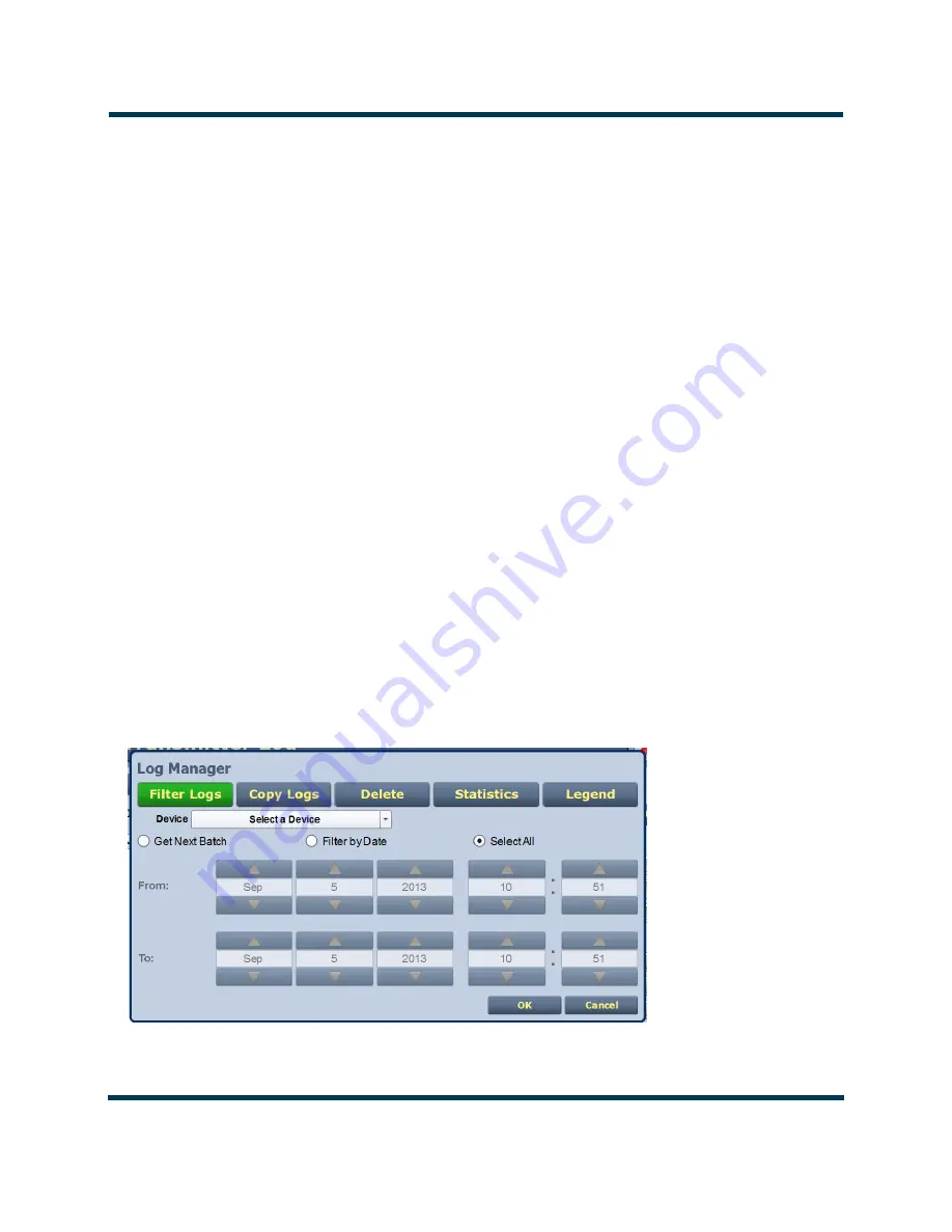
Managing the log

You can manage the VS1 AUI’s events log by clicking on the 

Log Manager

 button (see 

Figure 2.10

). 

This screen provides options to perform various event monitoring operations such as filtering, 
copying, deletion and statistical analysis. Click the 

OK

 button or the 

Cancel


button when done.

Figure 2.10: Log Manager options (Filter Logs shown)

Summary of Contents for VS1

Page 1: ...VS1 Transmitter Operations and Maintenance Manual Document NHB VS1 OPS 3 1 Issue 3 1 2013 10 01 Status Standard...

Page 2: ......

Page 3: ...Fax 1 207 947 3693 Customer Service 24 hour support 1 877 628 8353 Canada USA only 1 902 823 5100 International Email support nautel com Web www nautel com The comparisons and other information provi...

Page 4: ......

Page 5: ...ive stage 1 4 RF power stage 1 4 Operating the transmitter 2 1 User interfaces 2 9 Viewing Transmitter Log 2 23 Viewing AUI Tool Menu Panels 2 30 Viewing Real Time Meters 2 45 Managing Presets 2 51 En...

Page 6: ...abling and Operating the Orban Audio Processor 2 163 Routine maintenance 3 1 Scheduled maintenance 3 1 Replacing a damaged air filter 3 2 Performing on air checks 3 4 Replacing the exciter control PWB...

Page 7: ...and Maintenance Manual Issue 3 1 2013 10 01 Page vii Release control record Issue Date Reason 3 0 2012 01 10 Release 3 of product NARF65B and NAR65B 01 3 1 2013 10 01 Incorporated software version 4...

Page 8: ...VS1 Operations and Maintenance Manual Page viii Issue 3 1 2013 10 01...

Page 9: ...ee Section 4 Non standard maintenance on page 4 1 Performing procedures When using procedures in this manual perform each step in sequence If you are asked to see another section of this manual or ano...

Page 10: ...mentation suite includes the following documents VS1 Pre installation Manual VS1 PREINST Provides instructions and reference information needed when planning and preparing for the installation of a VS...

Page 11: ...AQ information sheets and information about field upgrades Documentation online and printed The website s NUG section provides online access to all the documentation for your VS1 Documentation is prov...

Page 12: ...VS1 Operations and Maintenance Manual Page xii Issue 3 1 2013 10 01...

Page 13: ...excess of 72 volts capable of causing a fatal electrical shock are present on or near parts bearing this label After turning off the ac power always perform a measurement to confirm that the power is...

Page 14: ...ption column of the Troubleshooting Manual s parts list s Do not cut crush or grind devices because the resulting dust may be hazardous if inhaled Unserviceable devices should be disposed of as harmfu...

Page 15: ...r of training courses covering the basic fundamentals of RF systems and transmitters and the operation and maintenance of the transmitter For more information about available courses and schedules go...

Page 16: ...autel does not offer first aid training since the hazards associated with high voltage and RF energy are not specific to the transmitter However the customer should provide first aid training to all p...

Page 17: ...ly near the feedline antenna and tower At some sites these fields may cause biological effects including the heating of body tissues Intense fields can also create dangerous high voltages on ungrounde...

Page 18: ...Lightning protection The transmitter is designed to resist lightning strike damage However intense or repeated strikes could damage the transmitter We recommend that you install lightning suppression...

Page 19: ...s SD s These are located in Section 5 of the VS1 Troubleshooting Manual Ac dc power stage See also electrical schematic Figure SD 1 The ac dc power stage converts the ac power source to a positive dc...

Page 20: ...PA PWB cooling fans and the dc dc converters on the power supply distribution PWB which provide 5 V and 15 V to circuitry throughout the transmitter PS distribution PWB See also electrical schematics...

Page 21: ...s contains monitoring and protection circuits to prevent transmitter damage under adverse or fault conditions including high speed SWR protection and interlock muting monitors the current value of var...

Page 22: ...input level generated by the exciter control PWB The output of the pre amp IPA PWB nominal 75W is applied to a directional coupler on the combiner PWB A10 which monitors this output level The directi...

Page 23: ...ter if applicable A third coupler provides an RF Monitor output J3 accessible on the rear panel of the transmitter which is a nominal 42 dBc 2 V rms 1250 W This signal is intended for use with a modul...

Page 24: ...VS1 Operations and Maintenance Manual Description Page 1 6 Issue 3 1 2013 10 01...

Page 25: ...TER SENSOR 1 POWER AMPLIFIERS COMBINER FAN x 3 SECTION FILTER HARMONIC 5V AC POWER SOURCE 180 264VAC 10MHz TCXO 10MHz EXTERNAL INTERFACE SELECT PROCESSOR ETHERNET AUDIO PLAYBACK AES EBU SCA RDS HIGH S...

Page 26: ...VS1 Operations and Maintenance Manual Issue 3 1 2013 10 01 Page 1 8...

Page 27: ...page 2 21 Viewing Transmitter Log see page 2 23 Transmitter Log Using the AUI see page 2 23 Transmitter Log Using the front panel see page 2 28 Viewing AUI Tool Menu Panels see page 2 30 Describing AU...

Page 28: ...RF drive source see page 2 103 ARM Reset see page 2 103 OS Recovery see page 2 104 Firmware Update see page 2 105 FM Polarity see page 2 105 Setting User Accounts see page 2 106 Setting User Type see...

Page 29: ...uts see page 2 144 Remote I O Settings Using the AUI see page 2 144 Remote I O Settings Using the Front Panel Display see page 2 151 Scheduler see page 2 155 Enabling the Scheduler see page 2 156 Enab...

Page 30: ......

Page 31: ...page 2 28 Clear Log page 2 28 Thresholds no user adjustment ARM Watchdog page 2 102 Console Select no user adjustment Calibration page 2 100 RF Drive Source page 2 103 ARM Reset page 2 103 OS Recover...

Page 32: ......

Page 33: ...Settings page 2 78 Enable page 2 80 Data Source page 2 80 Baud Rate page 2 80 RDS Level page 2 80 Limiter Settings page 2 82 Hard Limiter page 2 64 AGC Limiter page 2 65 2 Slope Limiter page 2 65 MOD...

Page 34: ......

Page 35: ...Reset page 2 94 Time Setup page 2 125 NTP Servers page 2 128 Audio Low Thresholds page 2 132 Setting Call Sign ID page 2 131 Email Configuration page 2 115 Exgine Settings page 2 118 Critical Paramete...

Page 36: ......

Page 37: ...ont panel display and navigational buttons see Front panel UI Remotely via a LAN connection using the advanced user interface AUI pages see Advanced user interface on page 2 16 See the complete menu h...

Page 38: ...set P and the transmitter s actual forward power Line 2 RF operating status ON or OFF the local LCL or remote RMT control status and the transmitter s reflected power level Line 3 operating frequency...

Page 39: ...the display will prompt its use X on menu and list screens exits to the next higher level screen on edit screens acts as a cancel function in some cases the display will prompt its use Turning RF on...

Page 40: ...Settings Edit Presets Output Power Edit the selected preset s output power page 2 68 User Settings Edit Presets Frequency Edit the selected preset s operating frequency page 2 70 User Settings Edit Pr...

Page 41: ...User Settings Set Clock Set precise time and date page 2 127 User Settings Pilot Sample Set the pilot sample level for the rear panel BNC connector page 2 133 User Settings LCD Settings Set the front...

Page 42: ...W Versions View the versions of installed software Reset Alarms Initiate an attempt to reset all alarms controlled by latched protection circuits page 2 90 System Settings Calibration Set calibration...

Page 43: ...ystem Settings Firmware Update Perform a software upgrade on the transmitter page 2 105 System Settings FM Polarity Set the polarity for FM deviation positive modulation signal yields positive frequen...

Page 44: ...ot etc Real time meters Detailed transmitter status and events log Presets Hardware configuration User accounts Software configuration Remote input output configuration Each AUI page provides informat...

Page 45: ...Status Click to shortcut to the Transmitter Status page see Viewing Transmitter Status on page 2 91 which provides current alarm and status details for the transmitter When the Status button is red on...

Page 46: ...t access restriction from read only no control and full administrative control Access the AUI using a web browser as follows 1 Configure your network settings Network Setup on page 2 111 2 On your rou...

Page 47: ...t from the previ ous login session Note The Nautel AUI is factory configured with a default login username and password Nautel recommends that you change the password to improve overall system securit...

Page 48: ...account information page 2 106 Menu System Settings Perform AUI and exciter reboots calibrate the exciter TCXO perform software upgrades and calibrate audio inputs levels if necessary factory calibrat...

Page 49: ...pages on page 2 20 Select Presets to load edit or save presets see Managing Presets on page 2 51 Select System Settings to access pages that allow rebooting of the AUI or active exciter cal ibration...

Page 50: ...low thresholds see User Settings AUI on page 2 109 Select Remote I O to access a page that allows assignation of remote digital inputs digital outputs and analog output see Remote I O Settings Using...

Page 51: ...the AUI You can view the VS1 s events log using the AUI s Log page see Figure 2 9 This page shows a configurable log of all transmitter events To view the Log page click the Log button in the bottom b...

Page 52: ...the display indicate specific information about the event Device indicates the origin device of the event Controller Exciter etc Event indicates the event name State indicates whether the event is act...

Page 53: ...ckbox to filter events based on a selected date and time range and the device type selected Click the OK button or the Cancel button when done Click the Cancel button to close this window and discard...

Page 54: ...move through the list using the scroll bar if applicable or the up and down arrow buttons to the right of the scroll bar The columns in the display indicate specific information about the events Devi...

Page 55: ...og page Click OK or Cancel to close this window Figure 2 14 Log Manager Legend Use the Reset button at the bottom of any AUI screen to attempt to clear any latching alarms that are holding the transmi...

Page 56: ...Events screen Use the up and down buttons to scroll through the list of alarms or events Refer to the VS1 Troubleshooting Manual to cross reference the alarm name to possible causes and troubleshooti...

Page 57: ...he transmitter Issue 3 1 2013 10 01 Page 2 29 View Software Versions front Panel UI The View SW Versions screen displays the current versions of the different software being used in the transmitter se...

Page 58: ...AM AM and AM PM correction screens see page 2 41 The VS1 AUI provides up to ten tool menu panels that you can choose to display on the AUI home page see Figure 2 17 Up to four tool menu panels can be...

Page 59: ...Tool Menu Description Reference Spectrum Displays a spectrum analyzer capable of monitoring various RF sections of the transmitter including the RF output See page 2 35 EQ Frequency Response Displays...

Page 60: ...mpensation being applied to the magnitude signal See page 2 41 AM PM Correction Tool menu available only when the transmitter is used with a VSHD exciter Displays the phase compensation being applied...

Page 61: ...cursor position To make fine adjustments use the backward and forward buttons see Figure 2 19 To enlarge reduce the instrument panel use the maximize minimize buttons Some instru ment displays show m...

Page 62: ...Manual Operating the transmitter Page 2 34 Issue 3 1 2013 10 01 Figure 2 20 Instrument Cursor Manipulation Figure 2 21 Instrument Panel Expansion Example Cursor Tools to move cursor and display inform...

Page 63: ...hown based on transmission mode and are defined by the latest versions of the following standards IBOC NRSC 5 European Standard ETSI EN 302 018 2 FCC CFR 47 Part 73 317 and IC BETS 6e Note While very...

Page 64: ...ault setting is 1000 Hz Span determines the start and stop frequencies of the analyzer with the carrier frequency always at the center Allowable range is 10 1200 kHz Default setting is 1000 kHz Averag...

Page 65: ...relative to the channel frequency Figure 2 24 EQ Frequency Response EQ frequency response See Figure 2 24 This panel displays the frequency response of the modulator s EQ filter Click on the panel to...

Page 66: ...response See Figure 2 25 This panel displays the impulse response of the modulator s EQ filter Click on the panel to display a cursor in the approximate area The cursor position time and magnitude is...

Page 67: ...dth Click on the panel to display a cursor in the approximate area The cursor position frequency and delay is noted in the upper right hand corner of the panel Click in other areas of the panel to pro...

Page 68: ...audio source Left and right audio content is displayed for all other audio sources The plot consists of a group of sequential samples to allow signal analysis In L and R mode the L R portion of the s...

Page 69: ...ed as instrument panels Figure 2 28 AM AM Correction AM AM correction This panel displays the amplitude correction being applied to the magnitude signal The x axis represents the signal amplitude and...

Page 70: ...epresents the phase shift correction applied for a given amplitude value Click on the panel to display a cursor in the approximate area The cursor position phase and LUT index is noted in the upper ri...

Page 71: ...dB with the reference representing the average power The average power is 0db The y axis displays the probability of exceeding that power level This plot can be used to assess the distribution of a g...

Page 72: ...display is representative of the forward path that will be transmitted Sub carrier group information is shown in the lower right section of the screen Displayed information includes the sub carrier gr...

Page 73: ...This section includes the following topics Describing the meter display on page 2 46 Accessing meter information see page 2 46 Identifying meter information on a specific sub device see page 2 47 Savi...

Page 74: ...ll within an operational range but is approaching design limitations A parameter value in the red section of a meter bar indicates the parameter is outside normal operating conditions Accessing meter...

Page 75: ...mation window in tabular format see Figure 2 33 3 To choose individual meters for display in the Meters window of the Home page Select the device type name in the Transmitter Layout panel and select t...

Page 76: ...ter Page 2 48 Issue 3 1 2013 10 01 Figure 2 34 Detailed Sub System Information Controller shown Figure 2 34 displays the status of the selected sub system as well as real time meter values The Alarms...

Page 77: ...ter list as the default for the current user account The symbol shows the default Press Save to overwrite the selected meter list with the currently displayed meters Press Load to display the meters s...

Page 78: ...meters Note This screen is for viewing purposes only and does not offer the same level of analytical features as the AUI s System Review page see Figure 2 33 on page 2 47 Forward forward power 1 2V VS...

Page 79: ...onal data power level frequency mode program input characteristics for the transmitter You can create presets and manage their various settings You can manage presets using the remote AUI see Managing...

Page 80: ...active operational preset or any preset that is referenced in the Remote I O menu as either a remote input or output Those links in the Remote I O menu must be deleted before the associated preset can...

Page 81: ...ed through an ac power cycle when the transmitter recovers from an ac power loss it loads the preset that was last activated On the Presets page an asterisk appears next to the preset name in the head...

Page 82: ...itional calibration settings This mode requires additional hardware FM HD also known as hybrid simulcast or low level combined this mode transmits the analog carrier FM modulated and the upper and low...

Page 83: ...carrier HD PA Volts for FM HD HD and DRM modes enter value in volts between 25 0 V and 53 0 V This value sets the drain voltage applied to the PAs in the RF power modules from their associated power...

Page 84: ...es result in improved efficiency but degrade the spectrum The default value is 50 V and typically does not change HD Power Boost for FM HD mode only Enable this setting to engage Nautel s digital Powe...

Page 85: ...etting See page 2 58 for additional configuration information Primary Digital this source allows for further configuration via Digital Level Audio Mode Mono L R Mono L Mono R Stereo 15kHz Lowpass Pree...

Page 86: ...eo applies to Left Right Mono Primary Digital or Secondary Digital sources selecting Stereo applies a 19 kHz pilot 15kHz Lowpass Filter applies to Left Right Mono Primary Digital and Secondary Digital...

Page 87: ...t be reduced by 1 Internal SCA1 2 Enable or disable the appropriate internal SCA SCA1 or SCA2 When enabled the settings listed below are active for the associated SCA signal 1 or 2 SCA1 or SCA2 Inject...

Page 88: ...Operations and Maintenance Manual Operating the transmitter Page 2 60 Issue 3 1 2013 10 01 Figure 2 41 Presets SCA Tab Note Refer to FCC guidelines for allowable modulation depth with SCAs or RDS enab...

Page 89: ...rmined by applying a formula to the station s call sign Additional information can be found at www nrscstandards org This selection applies to internal data sources only PS Code programme service code...

Page 90: ...receive a traffic bulletin The TP flag is used to allow the user to find only those stations that regularly broadcast traffic bulletins whereas the TA flag is used to signal an actual traffic bulletin...

Page 91: ...nance Manual Operating the transmitter Issue 3 1 2013 10 01 Page 2 63 Figure 2 42 Presets RDS Tab 1 of 2 Figure 2 43 Presets RDS Tab 2 of 2 Note Refer to FCC guidelines for allowable modulation depth...

Page 92: ...oss Preset displayed only if Action is set to Change Preset Select the preset from the drop down list that will activate upon the loss of a modulating signal post the timeout period Timeout Minutes se...

Page 93: ...60 default is 160 Gain enter value between 0 and 100 default is 50 L R Limiter This look ahead limiter can be applied to the signal immediately before the ste reo generator in the exciter It has a fix...

Page 94: ...o Tab 2 of 2 Saving presets Click the Save button to save preset information Deleting presets From the Presets page click the Delete button Highlight the preset you wish to delete noting you cannot de...

Page 95: ...preset Press the cancel X button to return to the previous menu Editing or creating presets When you select User Settings Edit Presets from the Main Menu see Figure 2 47 you can create up to 63 operat...

Page 96: ...s that can be edited are Output Power See Figure 2 50 on page 2 69 Use the up and down buttons to edit the output power in 1 W increments then press the accept checkmark button to save the change For...

Page 97: ...1131 993 1093 FM HD 19 dB 777 881 967 1087 944 1053 FM HD 18 dB 742 850 922 1043 896 994 FM HD 17 dB 705 815 875 997 843 939 FM HD 16 dB 669 780 828 951 791 884 FM HD 15 dB 631 741 780 903 735 825 FM...

Page 98: ...pt checkmark button to save the change Press the cancel X button to discard changes and return to the previous menu Figure 2 52 IBOC Mode screen IBOC Settings When you select IBOC Settings from the Pr...

Page 99: ...the cancel X button to discard changes and return to the previous menu PA Volts Use the up and down buttons to select a PA voltage between 6 and 53 V in 1 V increments then press the accept checkmark...

Page 100: ...io parameters see Figure 2 55 Figure 2 55 Main Audio menu Use the up and down buttons to scroll through the main audio menu options then press the accept checkmark or right arrow button to enter the s...

Page 101: ...rk button to save the change Press the cancel X button to discard changes and return to the previous menu Input Levels Use the up and down buttons to move the cursor to the desired audio input and the...

Page 102: ...the transmitter Page 2 74 Issue 3 1 2013 10 01 Figure 2 57 Input Levels editing screens Bal L R Level Select a level between 12 and 12 dBu MPX Level Select a level between 1 and 5 V peak to peak Digit...

Page 103: ...nable editing of the parameter Figure 2 59 shows all the editing screens for the Pilot Settings menu Within any of the editing screens use the up and down buttons to edit or toggle a parameter value n...

Page 104: ...gs menu Within any of the editing screens use the up and down buttons to edit or toggle a parameter value noting the minimum and maximum limitations indicated at the bottom of the display When complet...

Page 105: ...editing screens SCA Enable Select ON or OFF SCA Level Select a level between 0 and 20 SCA Freq Select a frequency between 20 and 100 kHz SCA Input Select a level between 12 and 12 dBu SCA Low Pass Se...

Page 106: ...e parameter Figure 2 64 on page 2 79 shows all the editing screens for the RDS Settings menu Within any of the editing screens use the arrow buttons to edit or toggle a parameter value noting the mini...

Page 107: ...VS1 Operations and Maintenance Manual Operating the transmitter Issue 3 1 2013 10 01 Page 2 79 Figure 2 64 RDS Settings editing screens...

Page 108: ...left arrows to move the cursor to the desired character Use the up and down arrows to edit the character PI Code Enter a hex value between 0x0000 and 0xFFFF Program Type Select the program type from v...

Page 109: ...01 Page 2 81 Figure 2 65 DI Code editing screens Art Artificial Head Select ON or OFF Compression Select ON or OFF Dynamic Select Dynamic or Static Stereo Select Stereo or Mono Figure 2 66 AF Data ed...

Page 110: ...e Figure 2 69 on page 2 83 2 Slope Limiter see Figure 2 70 on page 2 84 L R Limiter see Figure 2 71 on page 2 85 MPX RMS Limiter see Figure 2 72 on page 2 86 Within a sub menu use the up and down butt...

Page 111: ...2 83 Figure 2 68 Hard Limiter sub menu and editing screens Enable Select ON or OFF Limit Select a value between 0 and 160 Figure 2 69 AGC Limiter sub menu and editing screens Enable Select ON or OFF...

Page 112: ...ance Manual Operating the transmitter Page 2 84 Issue 3 1 2013 10 01 Figure 2 70 2 Slope Limiter sub menu and editing screens Enable Select ON or OFF Limit Select a value between 0 and 160 Gain Select...

Page 113: ...n press the accept checkmark button to save the change Press the cancel X button to discard changes and return to the previous menu Default time con stant is 5 000 s Use the up and down arrows to sele...

Page 114: ...editing screens use the up and down buttons to edit a parameter value noting the minimum and maximum limitations indicated at the bottom of the display as applicable When complete press the accept che...

Page 115: ...he time period of low audio based on the threshold setting after which the transmitter will take action Select a value between 0 and 14400 seconds 240 minutes Action Determines the action taken by the...

Page 116: ...X button to discard changes and return to the previous menu Copy another preset When you select Copy Another Preset from the Preset editing options screen you can copy the settings from another prese...

Page 117: ...a _ character underscore and one or two numbers that indicate the IBOC power injection ratio level s and finally the characters dBc e g PB 20 dBc See Figure 2 77 for examples of this naming conventio...

Page 118: ...Press the cancel X button to discard changes and return to the previous menu Resetting alarms You can attempt to reset any latching transmitter alarms that are holding the transmitter in an off air st...

Page 119: ...2 80 Transmitter Status page The Transmitter Status page displays all active transmitter alarms Alarms are listed by their host device Controller or Exciter alarm name and severity level a single oran...

Page 120: ...the AUI see page 2 99 Calibrating Exciter TCXO Using the front panel see page 2 100 From the remote AUI s System Settings page via the Main Menu options see Figure 2 81 you can reboot the remote AUI...

Page 121: ...es for various transmitter sub systems e g Controller Exciter etc see Upgrading Software on page 2 94 Audio Input Calibration Allows for calibration of analog and MPX audio inputs see Cali brating Aud...

Page 122: ...exciter click the Reboot Active Exciter button if the button is available highlighted To reset the standby exciter for dual exciters click the Reboot Standby Exciter button if the button is available...

Page 123: ...entical versions are shown in green different versions are shown in red You can also view the details of the previous upgrade by pressing the View Last Upgrade checkbox History displays a window conta...

Page 124: ...he peak meter value of each calibrated audio input analog left analog right MPX or MPX SCA Int SCA1 or Int SCA2 that is applied will be displayed Enter a valid calibration value and click Set to save...

Page 125: ...ut Calibration Screen Use the up or down arrow to place the cursor next to the desired audio input calibration item Bal L Cal Bal R Cal MPX Cal or MPX SCA Cal then press the accept checkmark button to...

Page 126: ...to Find Gain Press the Start button to automatically find the optimized gain while the transmitter is RF On and in the applicable preset mode injection level FM HD Low Inj Gain Applicable for FM HD mo...

Page 127: ...xciter TCXO from the System Settings options Figure 2 87 System Settings Exciter TCXO To automatically calibrate the internal reference for the exciter click the Start button The progress bar at the b...

Page 128: ...to TCXO Offset then press the accept checkmark button to enter the TCXO Offset screen Use the up and down arrows to set the TCXO offset value in ppm for the external 10 MHz source When complete press...

Page 129: ...urce see page 2 103 ARM Reset see page 2 103 OS Recovery see page 2 104 Firmware Update see page 2 105 FM Polarity see page 2 105 WARNING System settings are established at Nautel and should not requi...

Page 130: ...ontroller module If communication is lost for more than 30 seconds the transmitter will initiate an alarm and reboot the ARM To view the ARM Watchdog screen select System Settings ARM Watchdog from th...

Page 131: ...Exciter make sure the associated VS transmitter has been physically modified to operate with the VSHD exciter if necessary refer to the associated modification document IS11004A to modify and configur...

Page 132: ...u will also need to install a flash drive provided by Nautel in one of the two USB ports on the rear of the controller module A4 To view the OS Recovery screen select System Settings OS Recovery from...

Page 133: ...the FM Polarity screen select System Settings FM Polarity from the Main Menu see Figure 2 94 Figure 2 94 System Settings FM Polarity Screen Use the up and down buttons to toggle between Comp Freq Dev...

Page 134: ...and return to the home page The VS1 contains a default user account when it leaves the factory This account appears as Nautel Auto in the List of Users and has Super User permission level The default...

Page 135: ...r account click Add Enter the username click the OK button to accept then set the account information in the Settings section Click the Cancel button or X to discard changes and exit this menu Editing...

Page 136: ...6 Power Control Allows the user to change the power set point of the transmitter 7 Delete Logs Allows the user to remove log entries 8 RF On Off Allows the user to turn the RF output on and off 9 All...

Page 137: ...s from the Menu options Click X in the upper right corner to close this page and return to the home page Figure 2 96 User Settings Menu Network Setup Page Shown Via the User Settings menu the followin...

Page 138: ...2 125 Time Setup Allows for adjustment of the AUI clock s time date region and time zone see Setting the Clock on page 2 125 NTP Servers Allows for configuration and management of NTP servers see NTP...

Page 139: ...em manually using the transmitter s front panel In this case DHCP should be set to OFF Network Setup Using the Front Panel From the transmitter s front panel in local mode you can set or change networ...

Page 140: ...ess bar to the IP addresses of web servers hosting those sites If DHCP is set to OFF specify the address Masks an IP address and divides the IP address into network address and host address If DHCP wa...

Page 141: ...ions Local Area Network 4 In the Local Area Network Status open the General tab and choose Properties Scroll down and highlight Internet Protocol TCP IP Choose Properties 5 In the Internet Protocol TC...

Page 142: ...nnot be edited You must select Static IP to be able to edit the IP Address Subnet Mask Default Gateway and Nameserver fields If you are in DHCP mode these fields will be assigned automatically The Sta...

Page 143: ...e four fields noting the following Email Server In order to enter a server name e g mail nautel com at least one nameserver IP address must be entered see Network Setup on page 2 111 Port Number This...

Page 144: ...ick the check box and enter the appropriate Username and Password to allow this If the check box is not selected the Username and Password fields do not appear 2 When complete click Apply or click Can...

Page 145: ...em 2 When you click Add or Edit the screen in Figure 2 101 will appear This screen allows you to add or edit a Notification Name Recipient Email and define the alarm list by Device type Controller Exc...

Page 146: ...ply Digital Carriers Select On or Off Protocol Selects the E2X protocol to use UDP default or TCP Match this setting to the Exporter configuration Exgine IP Netmask and Gateway Configure the Exgine s...

Page 147: ...Manual Operating the transmitter Issue 3 1 2013 10 01 Page 2 119 Figure 2 102 Exgine Settings with VSHD installed only 4 When finished press Apply to accept your entries or press Cancel to ignore you...

Page 148: ...Enter the five fields noting the following Agent Port Enter the UDP port where the SNMP agent checks for requests The default setting is 161 If your transmitter is behind a firewall you must open this...

Page 149: ...ess Apply or press Cancel to restore the previous settings Traps Settings A trap is an unsolicited message sent by an SNMP agent to an SNMP client when an alarm changes state turns on or off The Enabl...

Page 150: ...this page you can press Capture Meters reads all meter values Capture Alarms reads all active alarms Capture Presets reads the current active preset and Capture Settings reads current settings e g act...

Page 151: ...al 10MHz Default shown External 10 MHz Input Using the AUI You can view the selection buttons for the external 10 MHz input on the the AUI s External 10 MHz screen see Figure 2 106 by selecting Extern...

Page 152: ...1 Figure 2 107 Front Panel External 10 MHz Input screen Use the up or down arrow to toggle between ON using external 10 MHz input and OFF not using external 10 MHz input then press the accept checkmar...

Page 153: ...time even during power outages The date and time needs to be set when the transmitter is first installed or after a power outage if the backup battery has failed You can set the date and time using th...

Page 154: ...t Panel on page 2 127 Time enter the hour 24 hour clock minutes up to 60 and seconds up to 60 Date select values from the drop down menus beside Day Month and Year 3 Enter the following location param...

Page 155: ...ge the time or date use the right and left arrow buttons to move the cursor to the desired field hours minutes seconds year month day and use the up and down arrow buttons to increase or decrease the...

Page 156: ...g servers Figure 2 112 User Settings NTP Servers Enabling NTP Enable the NTP function by selecting the Enable NTP checkbox Disable by de selecting the Enable NTP checkbox Press the Apply button to act...

Page 157: ...if the currently selected reference becomes unavailable IP Displays the IP address associated with the Remote Name In some cases the Remote Name could be the IP address Delay Displays the round trip d...

Page 158: ...transmitters security All data transfers are one way Nautel Transmitters are intelligent collecting data on nearly every aspect affecting your transmitters performance When this data is used by Nautel...

Page 159: ...4 allows users to set a name that identifies the transmitter on the AUI This identification will be displayed in brackets on the top transmitter banner of the AUI see Figure 2 115 Enter the call sign...

Page 160: ...ble audio source main or SCA level falls below the Trip Level setting default is 22 5dB for longer than the Timeout setting default is 20 sec an alarm will activate in the Status and Logs pages When t...

Page 161: ...140 Turn On Delay Setting see page 2 142 Ramp Up Speed Setting see page 2 142 Setting Pilot Sample Level From the front panel UI you can set the level of the pilot sample that is applied to the PILOT...

Page 162: ...ments Press the accept checkmark button to save the change Press cancel X to discard changes and return to the previous menu LCD Settings From the front panel you can configure the LCD display s contr...

Page 163: ...creens use the up and down buttons to edit a setting Press the accept checkmark button to save the change Press cancel X to discard changes and return to the previous menu Figure 2 119 LCD Settings Ed...

Page 164: ...or Menus Use the up and down buttons to move the cursor to the desired line item and then press the right button to enable editing Figure 2 121 on page 2 137 shows all possible editing screens for the...

Page 165: ...evious menu Default is 1 kHz Select a type None Sine Wave Sine Sweep or Band limited Noise Press the cancel X button to discard changes and re turn to the previous menu Select ON enabled or OFF disabl...

Page 166: ...feature FSK Deviation sets the amount of carrier shift from the original carrier frequency Select a value between 25 kHz and 25 kHz Repeat Interval determines how often the call sign is broadcast usin...

Page 167: ...VS1 Operations and Maintenance Manual Operating the transmitter Issue 3 1 2013 10 01 Page 2 139 Figure 2 123 Station ID Editing Screens...

Page 168: ...n Use the up and down buttons to toggle between FCC FM Mask ETSI FM Mask and No FM Mask The factory setting is FCC FM Mask Press the accept checkmark button to save the change Press cancel X to discar...

Page 169: ...he previous menu Figure 2 126 Audio Low Editing Screens Select a level between 100 and 0 dB in 0 5 dB increments Press the cancel X button to discard changes and return to the previous menu Default se...

Page 170: ...s disabled Press the accept checkmark button to save the change Press X to abort the reset and return to the previous menu Ramp Up Speed Setting From the front panel UI you can set the transmitter s...

Page 171: ...e Main Menu see Figure 2 128 Figure 2 128 Ramp up Speed Screen Use the up and down buttons to select a ramp up speed between 1 and 100 in 1 increments noting 100 represents approximately seven seconds...

Page 172: ...n on remote inputs and outputs and their factory default settings Remote I O Settings Using the AUI To view the Remote I O page see Figure 2 129 select Remote I O from the Menu options Click X in the...

Page 173: ...l AUI You can configure digital inputs 1 through 10 for one of a variety of control inputs Click the existing Channel bar to display the Select a Remote window see Figure 2 130 on page 2 146 From this...

Page 174: ...es the input or causes a reset as appropriate Rising Edge Turn Off Logic 1 high or rising edge de activates the input Falling Edge Turn Off Logic 0 low or trailing edge de activates the input Falling...

Page 175: ...puts AUI Using the Digital Outputs Page see Figure 2 131 you can configure up to 16 digital outputs that indicate either the presence of various alarms or the status of operator controlled circuits Na...

Page 176: ...ndicates the transmitter s RF power stage is off Preset Status 1 4 default The active preset s output will be indicated by a logic low The remaining non active preset outputs will be open collector Va...

Page 177: ...e output is false Local if the selected channel is Preset Preset 1 the drop down options are Output Low When Active Logic 0 low indicates the output is true Active Logic 1 high indicates the output is...

Page 178: ...ers cannot be changed to another meter are of a linear nature so that changes made to the Full Scale Voltage field allowable range is 1 6 V defaulted to 6 V will be reflected in the other fields accor...

Page 179: ...page 2 152 or Analog Outputs see on page 2 153 to view or edit detail on the selected inputs or outputs Digital Inputs Front Panel Using the Remote Inputs screens see Figure 2 135 you can configure up...

Page 180: ...Press cancel X to return to the previous menu If you save a change to a digital input via the front panel UI it will also be displayed on the AUI page Digital Outputs Front Panel Using the Remote Out...

Page 181: ...turn to the previous menu If you save a change to a digital output via the front panel UI it will also be displayed on the AUI page Analog Outputs Front Panel Using the Analog Outputs screens see Figu...

Page 182: ...rd Power Reflected Power Avg PA Volts or Total PA Current as well as the meter reading actual and full scale and the output pin voltage actual and full scale Press cancel X to return to the previous m...

Page 183: ...chedules as you desire To view the Scheduler page select Scheduler from the Menu options Figure 2 138 Scheduler page The left hand side of the Scheduler page displays a monthly calendar e g May 2012 U...

Page 184: ...Use the Repeat field to establish a repeating cycle for the rule e g every 24 hours Use the drop down menu to select the preset e g Current Settings for the rule The preset s power mode and frequency...

Page 185: ...he active preset will be the preset that was operating when the scheduler was disabled Enabling the Scheduler Front Panel To view the Scheduler enable disable screen see Figure 2 141 on the front pane...

Page 186: ...laylist Manager page has two selectable tabs Playlist see page 2 159 Streams on page 2 161 Figure 2 142 Playlist Manager Playlist Tab Shown The playlist or Shoutcast Livewire stream is typically used...

Page 187: ...nts and Available Files on USB Figure 2 143 Managing Playlist Files The Playlists section is used for adding Add button and deleting Delete button playlists The Playlist Contents section is used for i...

Page 188: ...B device is connected The USB drive must be formatted with a FAT32 file system Click the Refresh button to force an update of the list of files on the mounted USB The audio player supports only one US...

Page 189: ...f playing audio streams in either Shoutcast or Livewire format The audio player supports Shoutcast playlists and IP addresses for audio streams For a Shoutcast playlist enter the URL for the station F...

Page 190: ...he location 4 Click OK to add the audio stream or click Cancel to discard changes Editing or Deleting an Audio Stream 1 From the Streams tab see Figure 2 146 select the desired audio stream from the l...

Page 191: ...had a pre existing transmitter when you received your Orban Inside kit verify that the Orban card has been installed in the transmitter according to the NVLT Orban Inside Quick Guide QG12001 provided...

Page 192: ...udio Processor screen see Figure 2 147 use the up and down buttons to toggle between None and Orban Inside default factory seting is None Select Orban Inside to enable the Orban audio processor for us...

Page 193: ...lect Main Audio 4 Within the Main Audio screen see D in Figure 2 148 on page 2 166 scroll down and select Audio Processor This option appears only when the transmitter has been configured for Orban In...

Page 194: ...nsmitter turned on connected to a remote monitoring PC or laptop and in remote mode of operation navigate to the AUI s Main Menu Presets page 2 For the applicable preset click on the Other Settings ta...

Page 195: ...er the front panel UI see Selecting an Orban Preset Using the Front Panel or the remotely accessed AUI see Selecting an Orban Preset Using the Remote AUI on page 2 168 as follows Note Selecting an Orb...

Page 196: ...to the Orban Optimod 5500 manual for detailed information on the factory programmed presets available Figure 2 150 Selecting an Orban Preset Front Panel UI Selecting an Orban Preset Using the Remote A...

Page 197: ...con to enter the Audio Processor menu see Figure 2 153 on page 2 170 Figure 2 152 AUI Main Menu with Audio Processor icon WARNING When you open the Audio Processor page while the transmitter is on and...

Page 198: ...Audio Processor page click the Save button and then click the Save Preset window s Save As button Save As and Delete buttons not available for factory F presets When creating a new preset you can als...

Page 199: ...y will be overwritten by any edits made to subsequent presets A saved preset will display as a User preset designated by a U in the Load or Save screens User presets can be modified Tab Sections The f...

Page 200: ...current setting in the middle of the control and the available range of settings You can make adjustments either by clicking on the or buttons or by moving click hold and move mouse accordingly the gr...

Page 201: ...VS1 Operations and Maintenance Manual Operating the transmitter Issue 3 1 2013 10 01 Page 2 173 Figure 2 157 Audio Processor Menu EQ tab Figure 2 158 Audio Processor Menu Final Clipping tab...

Page 202: ...VS1 Operations and Maintenance Manual Operating the transmitter Page 2 174 Issue 3 1 2013 10 01 Figure 2 159 Audio Processor Menu Multiband tab Figure 2 160 Audio Processor Menu Compressors Tab...

Page 203: ...VS1 Operations and Maintenance Manual Operating the transmitter Issue 3 1 2013 10 01 Page 2 175 Figure 2 161 Audio Processor Menu Bandmix Tab...

Page 204: ...VS1 Operations and Maintenance Manual Operating the transmitter Page 2 176 Issue 3 1 2013 10 01...

Page 205: ...s is three months Local operating and environmental conditions may dictate more frequent visits while in remote sites less frequent visits may be acceptable Experience and system reliability will dete...

Page 206: ...the exciter control PWB battery on page 3 7 Replacing a damaged air filter If an air filter becomes damaged replace it as follows Parts and tools Replacement air filter Hex tool 3 mm Nautel Part HY93...

Page 207: ...VS1 Operations and Maintenance Manual Routine maintenance Issue 3 1 2013 10 01 Page 3 3 Figure 3 1 Air Filter Cleaning or Replacement Grill Filter PVC retaining plate...

Page 208: ...lized interference 2 Obtain the Proof of Performance document that was completed during factory testing and provided with the transmitter Use the front panel UI or the remote AUI to compare current tr...

Page 209: ...mA 101 mA IPA Curr 3 75 A 3 84 A 3 81 A PA1 Curr 11 4 A 10 2 A 9 60 A PA2 Curr 9 75 A 10 8 A 11 1 A PA3 Curr 9 77 A 11 1 A 11 3 A PA4 Curr 11 3 A 10 1 A 9 79 A PA Temp 32 5 C 33 1 C 36 0 C Temp 2 33 2...

Page 210: ...N A N A IPA Fwd 63 7 W 74 9 W 79 6 W Total PA Curr 42 1 A 42 0 A 41 7 A DC Power In 1697 W 1736 W 1794 W DC RF Eff 73 2 71 9 69 4 Avg PA Diss 101 W 110 W 125 W PA1 Bias 0 00 V 0 00 V 0 00 V PA2 Bias 0...

Page 211: ...to the transmitter Interval Every 12 months Parts and tools Replacement battery 3 V lithium coin cell 20 mm Nautel Part BBLT01 Panasonic CR2032 Procedure Perform the following steps to replace the bat...

Page 212: ...d continuity tester Procedure Perform the following steps to test the lightning protection systems 1 Test the continuity between ground available at your lightning arrestor and ground available on var...

Page 213: ...on or network computer with Windows and Internet Explorer Web browser CAT5 Ethernet cable Upgrade software tgz file provided via email or web download Preliminary checks 1 Determine the current softwa...

Page 214: ...emote control Laptop IP setup The following steps assume the operating system is Windows XP Adapt as required for computers with different operating systems 1 On the laptop go to Start Menu Control Pa...

Page 215: ...appear 2 If using a network computer open Internet Explorer and search for the IP address recorded in Step 2 of Transmitter IP configuration on page 4 2 The transmitter login screen should appear 3 A...

Page 216: ...tart Upgrade 3 After a successful load status is 100 complete and a message indicates a successful load cycle the ac power turn off then on on the VS1 4 This completes the software upgrade Restore the...

Page 217: ...s manual for operating instructions of the front panel UI and remote AUI interfaces Configuring the backup audio preset 1 From the transmitter remote AUI go to Menu Presets Load The Load Preset window...

Page 218: ...your Audio Source selection 6 To save your changes without affecting the original template preset s settings create a a new preset as follows see also Figure 4 3 on page 4 7 Click the Save New button...

Page 219: ...see Figure 4 4 on page 4 8 4 Open the Mod Loss Timeout field s drop down menu Select Yes This will display five sub fields Action Mod Loss Preset Timeout Minutes Timeout Seconds and Threshold Open the...

Page 220: ...nfiguration of the Primary Audio preset Return to the home AUI panel Notes SCA RDS and Pilot modulation levels are additive and contribute the audio level If their combined levels exceed the audio los...

Page 221: ...of multiple shutbacks within a pre defined period Cycling ac power Turning off disabling then turning on enabling the ac power source DHCP Dynamic Host Carrier Protocol DSP Digital Signal Processing U...

Page 222: ...and permanent loss of RF output power Typically follows repeated cutback foldback or shutback events SPI Serial Peripheral Interface A synchronous serial data link standard that operates in full duple...

Page 223: ......

Page 224: ...1 877 6NAUTEL 662 8835 Canada USA only or Phone 1 902 823 3900 or Fax 1 902 823 3183 Nautel Inc 201 Target Industrial Circle Bangor Maine USA 04401 Phone 1 207 947 8200 Fax 1 207 947 3693 Customer Ser...

Reviews: