


© by N&W GLOBAL VENDING S.p.A.
51
05-2015 3625 01
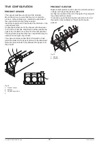
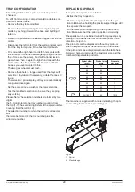
glassfRoNT lIghTINg boaRD
This board is intended to supply the glassfront lighting
LED’s for constant brightness.
The board is arranged in the slide-in shelf of payment
systems.
11
J1
J1
GND
ON / OFF
Vcc
GND
J2
J2
11
A1 K1 A2 K2 A3 K3
A1
1
2
Fig. 36
1- To the CPU board
2- To the lighting LED's
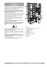
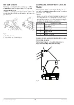
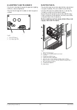
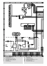
ElECTRIC PaNEl
The electric panel is accommodated in the compartment
of payment systems. The door switch can be directly
accessed. Remove the metal protection, to access the
connectors in the front of the electric panel.
Extract the electric panel to access the activation relay
of the cooling unit, the transformer, the line fuse and the
protection fuses of the transformer.
before replacing any fuse, please detach the power
supply cable from the mains.
7
8
9
10
1
2
3
4
5
6
Fig. 37
1- 230V / 24V transformer
2- Primary and secondary transformer fuser
3- Line fuse
4- Cooling unit ON/OFF relay
5- Radio interference suppressor
6- 24V connector
∿
anticondensate heating element (if any)
7- 220V connector
∿
glassfront anticondensate heating element
8- 24V CPU supply connector
9- Cooling unit connector
10- Main switch