


© by N&W GLOBAL VENDING S.p.A.
50
05-2015 3625 01
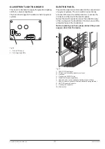
boaRD fUNCTIoNs
CPU boaRD
The CPU board is arranged on the slide-in shelf of pay
-
ment systems and intended to manage all components
of the machine.
The LEDs on the board can supply the following informa
-
tion during the operation:
-
the green LED (26) is flashing on and off during the
normal operation of the C.P.U. board;
-
the yellow LED (28) will turn on when 5 Vdc is applied;
-
the red LED (27) will turn on if the software is reset for
any reason whatsoever.
softwarE
upDatE
The machine is equipped with Flash EPROM’s that can
be electrically rewritten.
Use a proper program and system (personal Computer,
Up Keys or alike) to rewrite the machine management
software without replacing the EPROM’s.
attention !!!
It is recommended to disconnect the connectors of the
motors (J1) and the compartment lock (J2) from the
CPU board while downloading the software.
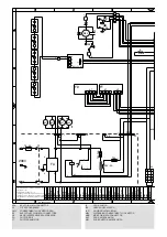
Fig. 35
1- (J4) Temperature probe (J4)
2- (J5) Validators (J5)
3- Battery jumper (pin 2 and 3)
4- (J16) not used
5- (J6) Direct selection keyboard (if available)
6- Input watchdog jumper (closed)
7- (J18) Up-key
8- (J7) Numeric selection keyboard
9- Programming button
10- (J8) Display
11- (J9) Numeric keyboard supply
12- (J10) RS232 serial port
13- (J12) EXE/BDV payments
14- (J11) MDB payments
15- (J13) Connector
can
-
bus
16- (J14) Connector
can
-
bus
17- Jumper
can
-
bus
(closed)
18- Buzzer
19- (J15) Photocells (if any)
20- (J17) Not used
21- (J21) Not used
22- (J22) RAM data expansion (optional)
23- (J20) 24Vac power supply
24- (J19) To the current regulator board
25- (J2) Compartment lock
26- DL3 “RUN” green Led
27- DL2 “RESET” red Led
28- DL1 “+5V” yellow Led
29- (J3) To the external programming and relay
30- Battery
31- (J1) Tray motors


