background image

3.5 Tool constant settings

6

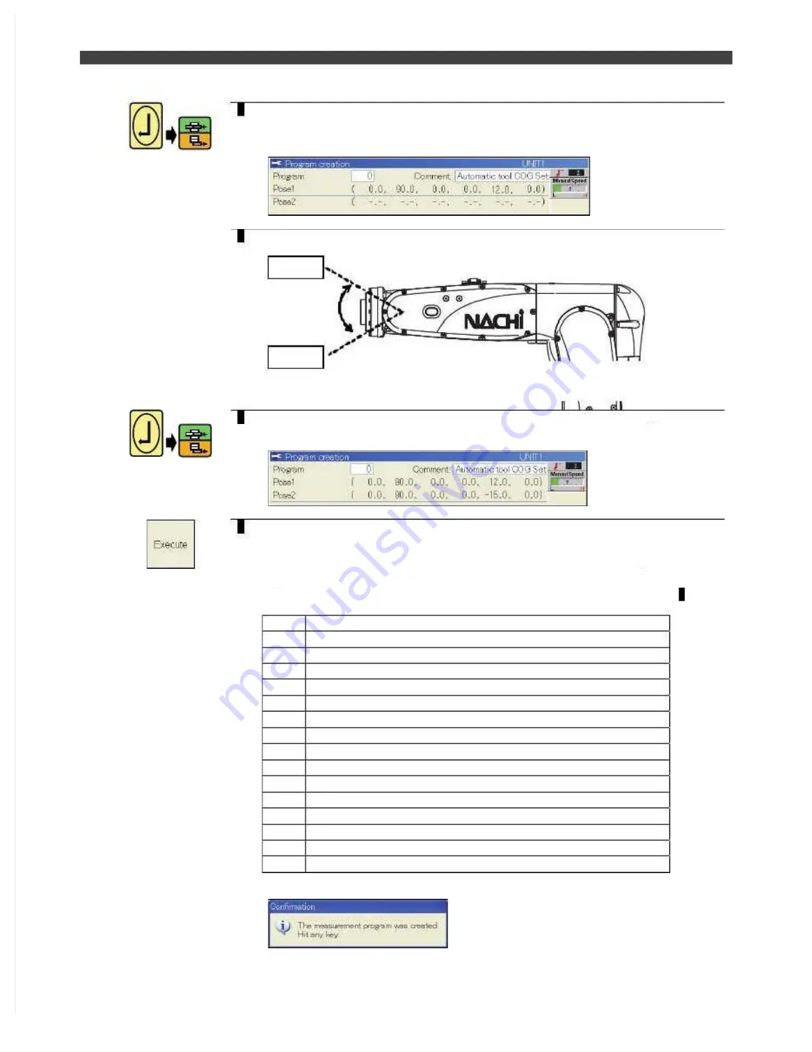
Align the cursor with the Pose 1 field, and press the [Enter] key and [O.WRITE/
REC] key.

>>The first posture (Pose 1) is now registered. The angle data loaded for the axes is
displayed as shown below.

7

Next, make a major change to the posture. At this time, change the wrist posture
as much possible.

Move  the  J5  up/down  and  record  the  position  with
unbalance torque is being added to the J 3 and J6

Pose1

Pose2

8

Align the cursor with the Pose 2 field, and press [Enter] key and [REC] key.

>>The first posture (Pose 2) is now registered. The angle data loaded for the axes is
displayed as shown below.

9

This completes the registration of two of the points required. Press the f12
<Execute> key.

>>Based on the two postures registered in  this way, the program shown below
consisting of a multiple number of steps for initiating the automatic center of gravity
(COG) and weight of tool settings is now generated automatically. The program No.
which is automatically generated at this time is the one which was specified in 4.

Comment data

Pose 1 point

Point where J6 axis is positioned when it has moved by 10 degrees

Pose 1 point

Point where J5 axis is positioned when it has moved by 10 degrees

Pose 1 point

Point where J3 axis is positioned when it has moved by 10 degrees

Pose 1 point

Pose 2 point

10 

Point where J6 axis is positioned when it has moved by 10 degrees

11 

Pose 2 point

12 

Point where J5 axis is positioned when it has moved by 10 degrees

13 

Pose 2 point

14 

Point where J3 axis is positioned when it has moved by 10 degrees

15 

Pose 2 point

16 

END instruction

>>Upon completion of the automatic generation of the program, the following pop-up
message is displayed. Press any key.

The  poses  (robot  positions)  were  recorded  directly  by  following  the  instructions  set  forth  above,  but  an
alternative to this is to teach a program in which these positions have been recorded ahead of time, and
then call that program.
Since a program can be used over and over again once it has been taught, this method is preferable in
cases such as a tool change application where the work involved in setting the  center of gravity and weight

Summary of Contents for EZ-CFDL Series

Page 1: ...n using this robot observe the low related with industrial robot and with When using this robot observe the low related with industrial robot and with safety issues in each country safety issues in each country This operating manual must be given without fail to the individual who will be actually This operating manual must be given without fail to the individual who will be actually operating the...

Page 2: ......

Page 3: ...hapter 2 Transportation and Installation Transportation and Installation 2 1 2 1 From the installation work to the teaching work 2 1 From the installation work to the teaching work 2 1 2 2 2 2 Installation of this controller Installation of this controller 2 2 2 2 2 2 1 2 2 1 Environment 2 2 Environment 2 2 2 2 2 2 2 2 Install dimension Install dimensions of robot controlle s of robot controller r...

Page 4: ...lifications ns 3 52 3 52 3 7 3 3 7 3 How to change the How to change the passwords passwords 3 53 3 53 3 7 4 3 7 4 How to set the operator qualifications class at power on How to set the operator qualifications class at power on 3 54 3 54 3 8 3 8 I O area mapping function 3 55 I O area mapping function 3 55 3 8 1 3 8 1 I O area map I O area mapping ping 3 55 3 55 3 8 2 3 8 2 Relation with software...

Page 5: ... User help function 3 95 3 20 1 Outline 3 95 3 20 2 Available image file formats 3 95 3 20 3 How to register the image file 3 96 3 20 4 How to display the user help image 3 97 3 20 5 Setting file USERHELP con 3 99 3 20 6 Trouble shooting 3 99 Chapter 4 Preparations for automatic operation 4 1 Home position registration 4 1 4 1 1 Home position 4 1 4 1 2 Home position registration by referencing the...

Page 6: ...procedure 7 3 7 2 1 How to initialize the memory of the controller outline 7 3 7 2 2 Enabling the Synchro motion function 7 6 7 2 3 Setting the Operation standard and the Speed standard 7 7 7 2 4 Setting the installation position and the angle of the mechanisms 7 9 7 3 Supplemental items 7 11 7 3 1 The Distance based shortcut motion and the Speed Pilling Rate based shortcut motion 7 11 7 3 2 Chang...

Page 7: ...rd UM396 8 13 8 8 2 Pin layout of TBEX1 and TBEX2 8 14 8 8 3 JP1 setting Selection of the power source for the Emergency Stop circuit 8 14 8 8 4 Setting of the SW1 Robot number 8 15 8 8 5 Mini I O 8 points 8 points 8 16 8 8 6 When using CC Link DeviceNet etc Fieldbus options 8 16 8 9 CFDL memory format operation Initialization 8 17 8 9 1 How to register the Mechanisms Robots to the robot controlle...

Page 8: ...Table of Contents NOTE ...

Page 9: ...ure the operators safety 1 1 For safely use the robot system 1 1 1 1 1 Symbols used in all instruction manuals 1 1 1 1 2 General precautions for safely use the robot system 1 2 1 1 3 Safety Measures on manipulator 1 4 1 1 4 Safety measures in teaching and inspection 1 5 1 1 5 Safety measures in test run 1 8 1 1 6 Safety measures in auto operation 1 8 1 1 7 Brake Positive Release 1 10 1 1 8 Movemen...

Page 10: ...ぺージあわせのため白文字 白文字のため印刷されないなので気にしないでください 削除しないでください ...

Page 11: ...y or serious injury if handling is mistaken Always observe these precautions to safely use the robot WARNING Precaution indicating cases where the operator could be subject to fatalities or serious injuries if handling is mistaken Always observe these precautions to safely use the robot CAUTION Precaution indicating cases where operator could be subject to injury or physical damage could occur if ...

Page 12: ...th the robot placed in a posture where the all axes are aligned to the reference position The correction value is input by pressing Enter followed by REC These values are input for each axis Encoder value in hexadecimal notation after correction Angle deg of each axis Data Input Use this method when the encoder correction values are already known An encoder correction value which is already known ...

Page 13: ...recommended to record this Reference pose a pose in which the all axes are aligned to the reference positions to program 9999 as a Reference position check program This program is convenient to check if the all axes of the robot are correctly set to the reference position respectively WARNING This work includes some jobs that should be conducted with the motors ON Consequently be sure to conduct t...

Page 14: ...xis 5 zeroing pin Inserting position of Axis 5 zeroing pin Inserting position of Axis 3 zeroing pin Axis 3 zeroing pin Axis 6 zeroing block Axis 4 zeroing block Axis 1 zeroing pin Axis 2 zeroing pin Inserting position of Axis 2 zeroing pin Inserting position of Axis 6 zeroing block Inserting position of Axis 4 zeroing block Inserting position of Axis 1 zeroing pin ...

Page 15: ...tool length can be ascertained automatically using the already created program Length Angle Center of gravity COG And weight Moment of inertia Maximum rotation radius This constant is for setting the inclination of the tool tip in the TCP coordinate system using the X Y and Z axis rotation components It proves useful since when teaching the tool can be operated manually in the direction in which i...

Page 16: ...Upon completion of the settings press the Complete key The settings are now saved in the constant file Operation returns to the machine constant menu screen 3 5 1 Tool name With an application which involves the use of a multiple number of tools the parameters become more comprehensible if the name or model for instance is registered here first It is not required to set the tool name The initial s...

Page 17: ... rotation around the X Y and Z axes The coordinate system defined by these parameters is called the tool coordinate In the wrist coordinate system the center of the tool installation surface serves as the zero point and the direction in which this surface is pointing serves as the Z direction as is shown above Measure the tool length which was measured in accordance with the definition given above...

Page 18: ... tip position based on the wrist coordinate system Input the X Y and Z value See the example in the next page 4 Upon completion of the settings press the Complete key The settings are now saved in the constant file Operation returns to the machine constant menu screen NOTE The Complete operation writing operation to the internal memory cannot be executed if the Motor Power Source Circuit is ON Tur...

Page 19: ...180 deg Around y z axis No rotation 0 deg TOP VIEW INFO Normally accurate motion path of the TCP is not required for most of the handling application Only the accurate position repeatability is required So the setting accuracy of the TCP coordinates does not matter However if the application requires accurate motion path please set the TCP position accurately referring to Setting the tool length a...

Page 20: ...th is x y z 210 0 110 And if the Wrist coordinate system is rotated like the following the desired direction of the tool coordinate system is acquired The order is z y x X axis 180 deg Y axis 90 deg Z axis No rotation 0 deg TOP VIEW Tool coordinate system Z Y X TCP x y z 210 0 110 y 0 No offset Wrist coordinate system Y Z X x 210 The origin 0 0 0 of the Wrist Coordinate System is the flange center...

Page 21: ...ing a high accuracy Record all the steps with linear interpolation ON Although it has nothing to do with calculating the tool length this comes in handy in when checking the results in7 2 On the tool constant setting screen for the desired tool number press the Easy Setting key The tool length automatic setting screen such as the one shown below now appears 3 If any other screen has appeared press...

Page 22: ...nd press Enter key At this stage only the display is updated and the data is not yet stored in the constant file 8 Upon completion of the settings press the Complete key The settings are now saved in the constant file Operation returns to the machine constant menu screen 9 Upon completion of the settings check them Exit the constant menu and try check go back of program taught in 1 Sharp tip fixed...

Page 23: ... target to the sharp end fixed to the ground Sharp tip fixed on the ground Tool tip before deformation 2 Next it is necessary to teach the task program with the tool after deformation Carry out teaching 1 step the task program in the same manner as in the above 1 Set the tool posture same as that taught in the above1 Tool tip before deformation Sharp tip fixed on the ground 3 In the tool constant ...

Page 24: ...l length is not stored in the constant file yet 10 After the setting press Complete key The set contents are stored into the constant file The screen goes back to the machine constant menu screen 11 When the tool constants are changed following pop up window will be displayed When the taught position for the robot in the taught program should be shifted according to the modified tool constants sel...

Page 25: ...e performed with the tool coordinate and by Service Program Conversion XYZ shift Since all other operations and the path used during playback are not affected in any way the initial setting 0 degrees for all directions may be used as is Since it is often difficult to measure the tool angle the following simple setting function has been provided Follow the setting procedure below Simply setting the...

Page 26: ... press the Enter key At this stage only the display is updated and the data is not yet stored in the constant file To set the value accurately it is also possible to re enter the value of 180 0 manually instead of 179 4 for example 6 Upon completion of the settings press the Complete key The settings are now saved in the constant file Operation returns to the machine constant menu screen 7 Upon co...

Page 27: ...has not yet been read do not set the center of gravity COG and weight of tool but use the initial settings as is and continue until the end of the setup is reached After reading the Basic Operations Manual proceed with these settings again without fail Setting the center of gravity COG and weight of tool automatically Operate the robot in a predetermined manner calculate the torque generated from ...

Page 28: ...bar graph on the torque monitor at the bottom right of the screen A posture in which the bar graph is the longest for the J3 J5 and J6 axes is the ideal one However pay particular attention to the resulting movements of the cables since a posture in which tension is applied to the application cable or which causes the cables to rub against the robot body will adversely affect the accuracy J3 J5 J6...

Page 29: ...at this time is the one which was specified in4 1 Comment data 2 Pose 1 point 3 Point where J6 axis is positioned when it has moved by 10 degrees 4 Pose 1 point 5 Point where J5 axis is positioned when it has moved by 10 degrees 6 Pose 1 point 7 Point where J3 axis is positioned when it has moved by 10 degrees 8 Pose 1 point 9 Pose 2 point 10 Point where J6 axis is positioned when it has moved by ...

Page 30: ...ns were recorded in the program they re ignored Only the move command will be picked up 13 The procedure is now the same as in 9 2 Executing the center of gravity COG and weight of tool settings 14 Finally measure the center of gravity COG and weight of the tool The program for measuring the center of gravity COG and weight of tool which was created before must now be executed Execute the measurem...

Page 31: ... of these values in the Service load setup field If the service load is not known there is no need to set it The center of gravity COG and weight of tool setting function measures the tool and service load together as if the load were concentrated on the tool 19 Press the f12 Execute key Waiting appears as the execution status This indicates the status in which the playback operation for collectin...

Page 32: ...elding with an arc welding torch elding torch This is necessary to use the weaving function This is necessary to use the weaving function Sealing Sealing For For sealing sealing with with a a sealing sealing gun gun Palletizing Palletizing For For palletize palletize function function Table 3 10 1 Table 3 10 1 Items settable by unit Items settable by unit Item Description Item Description Usage1 U...

Page 33: ...of 1 and its usage are described hereinafter its usage are described hereinafter Currently Currently 2 3 and 2 3 and 4 are not available 4 are not available in the CFD controller in the CFD controller Setting Procedure Setting Procedure 1 1 First input R314 and select First input R314 and select operator qualification operator qualification EXPERT EXPERT or above or above 2 2 Select teach mode and...

Page 34: ...en a general purpose output signal is set is set 1 1 In teach mode the set output signal can be turned ON OFF manually In teach mode the set output signal can be turned ON OFF manually Using the signal assigned to signal 1 of the clamp key output as the reference Using the signal assigned to signal 1 of the clamp key output as the reference signal output is performed by switching between O signal ...

Page 35: ...rograms from the list and then put the check marks for the axes to be used for the calculation When the Complete key is pressed the software limit operating range is automatically When the Complete key is pressed the software limit operating range is automatically calculated If it is necessary set the calculated If it is necessary set the margin parameters and then save the result margin parameter...

Page 36: ...cursor with the target axis and operate the robot manually to move each axis to a position you want to set for the software limit 3 Press Enter key and then press REC key The software limit values are overwritten 4 Press the Complete key The software limit values are registered and the 3 Machine Constant menu reappears CAUTION By moving robot check the relationship between the rotating direction a...

Page 37: ...Setting procedure 1 Open Service Utilities 25 Robot Diagnosis 6 User Error The following screen is displayed Edit the existing user error Copy the content of the current user error to the other error number Delete initialize the current user error 2 After setting the respective items press Complete The settings are saved to the internal memory 3 When the Input Signal is turned ON the error window ...

Page 38: ...is setting item is available only in the system software FDV03 21 or after Error reset The information display can be turned OFF in case of error rest motors ON program start or teach pendant operation etc The information display is not turned OFF when input signals are turned OFF Clear info disp Signal off The error reset motors ON program start or teach pendant operation cannot turn OFF the info...

Page 39: ... The settings will be saved in the memory Table 3 16 1 Operation condition Item Description Ground angle fixed motion This setting decides if the 3rd axis will move when the 2nd axis moves Disabled The 3rd axis will not move when the 2nd axis moves Enabled The 3rd axis will move to keep its angle against the ground when the 2nd axis moves NOTE This is available in the system software FDV03 17 or a...

Page 40: ...ing Select the operator class EXPERT or higher in advance Setting procedure 1 Open Constant Setting 3 Machine Constants 36 Playback speed limit 2 The setting is protected by a password Touch the Password ICON Enter the password For the password numbers of 8 digits or less and or can be used The initial setting factory setting is no password When this screen is closed it is necessary to enter the p...

Page 41: ...the current password The inputted numbers are displayed as If this password is not correct the password cannot be changed In case of no password leave this item empty New password Enter the new password For the password numbers of 8 digits or less and or can be used In case of no password leave this item empty IMPORTANT If you forget the password it is impossible to release the protection Please b...

Page 42: ...on and the return operation is not performed operation is not performed If the distance has been set t If the distance has been set to 0 mm the return decision is not o 0 mm the return decision is not based on the distance based on the distance If the angle has been set to 0 degrees the return decision is not based on the angle If the angle has been set to 0 degrees the return decision is not base...

Page 43: ...6 S6 MOVE MOVE S7 S7 MOVE MOVE S8 S8 COLDET 0 1 9 COLDET 0 1 9 S3 S3 MOVE MOVE When not detecting the collision When not detecting the collision Collision detection Collision detection When detecting the When detecting the collision collision S9 S9 MOVE MOVE R o R o b o t p r o b o t p r og r a m g r a m 3 MOV 3 MOVE E 4 MOV 4 MOVE E 5 COL 5 COLD D ET 1 1 7 Start the detection ET 1 1 7 Start the d...

Page 44: ...Machine robot Tool or User NOTE The user coordinate system must be defined in advance NOTE The user coordinate system must be defined in advance Number Number In In case case of of T Tool set ool set the the tool number tool number In case of In case of User set the user User set the user coordinate system number coordinate system number Hold Hold variable variable Select Select the the type type ...

Page 45: ... For details refer to 3 19 3 3 19 3 Settings for the conditions for Settings for the conditions for the Collision detection the Collision detection 3 3 Shelter Shelter step step Designate the shelter step Designate the shelter step number number 1 10000 1 10000 If 10000 is set the robot will stop after detecting the If 10000 is set the robot will stop after detecting the collision with an error me...

Page 46: ...FN31 COLDET function it is possible to stop the robot in case of fault When the collision is detected in the detection area that is sandwiched by the FN31 COLDET functions the following message is displayed and the robot will stop the playback motion Code A2362 Message Detected the collision interrupt Content Since the collision detected the interrupt the robot was stopped Counter measure Please c...

Page 47: ...the USB memory of the CPU board Without the USB memory the user help screen cannot be displayed 3 20 2 Available image file formats The available image formats for this user help function is shown in the following table Format BMP JPEG GIF File name extension bmp jpg jpeg gif Image size 1280x1024 pixels or less 640x480 is recommended Number of colors 24 bit color or less File path The folder in th...

Page 48: ...tion window Using up down cursor keys to select the registration number and then press Enter In this example 1 is selected 3 The cursor will move to the right side of the screen Select the desired image file using cursor key and press Enter In this example an image file HELP ZEROING123 jpg placed in the RC Ex Mem external USB memory device is selected Please be sure that the file name extension is...

Page 49: ... an example let s assign the software key in the Teach mode However the User Help software key can be assigned both for the Teach mode and the Playback mode Operating procedure 1 Press f Key Entry in the Constant Setting 38 User Help screen 2 Input 2520 for the f1 key and press Enter Then press Complete The setting is saved in the internal memory 3 The USER HELP software key is displayed as the f1...

Page 50: ... Only the differences from the program reference system will be described below 1 Set Position to Manual The setting screen changes as shown below 2 Turn on the motor power servo power and move the robot by manual operations to the position which is to serve as the home position Once the position has been determined release the enable switch Alternatively turn off the motor power 3 Press the Curre...

Page 51: ...l The setting screen changes as shown below 2 Move the cursor to the Territory field input the position of each of the axes directly in degrees and press the Enter key It is possible to input positions that significantly exceed the software limits operating ranges of the axes Some axes which have been excluded from being the target of inspection for their home positions can be supported by setting...

Page 52: ...e When all the mechanisms included in a unit are in the registered area the unit is considered within the range of start enable area For the management unit all the mechanisms in a system are to be checked 4 2 1 Registering the start enable area Note that the operator qualification of EXPERT or higher is required for this operation 1 Select the teach mode 2 Select Constant Setting 9 Area 3 Possibl...

Page 53: ...This section describes how to check if the unit is in the start enable area 1 Switch the unit that checks if the robot is in the start enable area to the current unit by pressing Enable UNIT MECHANISM key 2 When the current unit is within the start enable area the following icon appears in the Variable status display area If not this icon does not appear 4 2 3 Checking which axis is out of the sta...

Page 54: ...robot operating envelop defined as operating envelop defined as box or sphere box or sphere Fig 4 4 1 Fig 4 4 1 Image of Image of Interference T Interference Territory erritory Up to 16 interference territories can be registered per unit the unit in which the programs is configured Up to 16 interference territories can be registered per unit the unit in which the programs is configured IMPORTANT I...

Page 55: ...th Program No and Step No then input the number of the program and step No the program and step No prepared in prepared in 1 1 and press the Enter key and press the Enter key This step must indicate a move command without fail This step must indicate a move command without fail The data recorded in the program and The data recorded in the program and step is now called and step is now called and i...

Page 56: ...waits for interference interference area input signal ON area input signal ON 12 12 Next Max radius of tool Next Max radius of tool parameter needs to be defined parameter needs to be defined 4 5 6 Max Radius of tool 4 5 6 Max Radius of tool When checking the interference When checking the interference between the robot tool and between the robot tool and interference territory tool shape is inter...

Page 57: ...ory and Territory position input signal is turned ON While waiting right position input signal is turned ON While waiting right message will be displayed message will be displayed 4 4 After R 2 g After R 2 goes out of the oes out of the interference territory interference territory and T and Territory position erritory position input signal is input signal is turned ON R turned ON R 1 1 turns OFF ...

Page 58: ...4 4Interference Territory registration NOTE ...

Page 59: ......

Page 60: ...ork Network setting setting To enable this controller to communicate on Ethernet networks the network configuration including this To enable this controller to communicate on Ethernet networks the network configuration including this controller shall be set at first There are following two methods for that controller shall be set at first There are following two methods for that Select an appropri...

Page 61: ...er Files are transferred using the operation menu of this controller Files are transferred using the operation menu of this controller This controller works as an FTP client the node to start the FTP This controller works as an FTP client the node to start the FTP requirement requirement FT FTP P File transfer File transfer PC PC FTP client FTP client This c This controller ontroller Operator Oper...

Page 62: ...ion Information Server Server IMPORTANT IMPORTANT When system memory protection function has been set to enabled When system memory protection function has been set to enabled system memory protection function is needed to be changed disabled before the system memory protection function is needed to be changed disabled before the setting of section setting of section 5 2 1TCP IP setting 5 2 1TCP I...

Page 63: ...ored Computer name This is the computer name to identify this controller on the network IP address This is the IP address to identify the TCP IP host this controller on the network Subnet mask This is the data to define the border mask for IP address so that TCP IP can distinguish Network ID and Host ID Default gateway Specifies the gateway address if communication with the host in some other netw...

Page 64: ...sword The account that has the administrative access right will be prevented from accessing it but only the account specified as an anonymous access can access it Connectable number Sets the maximum connectable number to one server at the same time The number can be from 16 to 1000 Timeout period Sets the time to disconnect the inactive user from the server on the second time scale The timeout per...

Page 65: ... keys together to open the soft keyboard 3 Point the cursor to password and then input the password 4 Point the cursor to password and then input the same password as 3 5 Upon completion of the setting press f12 Complete The completion of user registered screen shown below appears 6 When the User deleted point the cursor to any of one User name or Password or Password and then press f9 Delete user...

Page 66: ... Server Host Before using the FTP client function it is necessary to set a host which will be the FTP sever for connection according to the following steps Up to 2 FTP servers can be connected to this controller This is an important setting and must be made by your network administrator Operator qualification as the SPECIALIST is necessary Registrations of FTP Server Host 1 Press f4 File When soft...

Page 67: ...ting such as TCP IP or FTP shall be completed beforehand The details are given in 5 2 Ethernet setting FTP PC FTP client Robot controller Operator FTP server Fig 5 4 1 File transfer with robot controller as FTP server IMPORTANT Be careful when files are transferred to this controller during the playback operation Do not transfer constant files or initial value files which directly affect the robot...

Page 68: ...5 4File transfer FTP server NOTE ...

Page 69: ...erations that are not available in case of Compact TP please refer to the other chapters In that case FD on Desk Light is necessary 6 1 Setup of the robot 6 1 6 1 1 Encoder reset and encoder correction 6 1 6 2 Setup of the controller 6 5 6 2 1 Display language 6 5 6 2 2 Ethernet TCP IP 6 6 6 2 3 Teach pendant setting LCD Contrast 6 8 ...

Page 70: ......

Page 71: ...ased on the Spped Piling Rate method No Name Motion Display example 1 Simultaneous No H No synchromotion This is the same with the normal motion The synchro motion is not executed Each mechanism moves independently H is not displayed 2 Synchro motion With H With synchromotion The synchro motion is executed All mechanisms will follow the motion of the Operation Standard Mechanism H is displayed The...

Page 72: ... referring to the motion speed of the Speed Standard mechanism For example if the UNIT have a 6 axes robot M1 and a 1 axis positioner M2 and the robot is selected as the Speed Standard Mechanism it is necessary to teach the motion speed of the robot When playing back the teaching program the positioner will synchronize with the motion speed of the robot start with the robot and stop with the robot...

Page 73: ... the Teach Pendant 8 10 8 6 Connection of the External Devices 8 11 8 6 1 Connection of the cables 8 11 8 6 2 How to start up the controller from the external PLC and etc 8 11 8 7 Connection of the Primary power and the grounding CFDL 8 12 8 7 1 Before connecting to the Primary Power 8 12 8 7 2 Processing of the Power cable 8 12 8 7 3 Grounding 8 12 8 8 Sequence board UM396 8 13 8 8 1 Sequence boa...

Page 74: ...ion of the tool 8 25 8 11 Encoder reset and encoder correction 8 26 8 12 Setting of the Tool Constant 8 27 8 12 1 Tool length 8 27 8 12 2 Tool angle 8 29 8 12 3 Tool COG Mass 8 30 8 12 4 Tool inertia moment 8 32 8 12 5 Tool Maximum Rotation Radius 8 32 ...

Page 75: ... of the back connector at CFDL4 Two robots 2 1 IMPORTANT About slot ID when using the fieldbus board In case of equipping the Fieldbus board such as DeviceNet or CC LINK etc to the slot for option then please refer to the figure up with Slot ID and select 4 3 2 1 4 3 2 1 Slot for option x1 CPU Board 2 1 2 1 Slot for option x3 Sequence board 1 Sequence board 1 1 2 O N OFF OFF 1 2 O N ON OFF 1 2 O N...

Page 76: ...r more away from the wall 2 Install the controller so that the height of power switch from work floor will be 0 6m to 1 9m 3 CFDL controller is not dust proof or drip proof structured In case of using it under the dust or mist environment then please add the following option Controller protection box In case of using the protection box the condition of the ambient temperature is 0 to 30 For CFDL1 ...

Page 77: ...EZ series 8 3 Installation of the Robot EZ series Please refer to below instruction or 2 3 Installation of the robot regarding with the installation condition Standard specification EZ03V4 02 EZ03F4 02 EZ02V6 02 EZ02F6 02 SEZEN 093 ...

Page 78: ... of not matching the number then robot cannot be operated Connect the CFDL controller and the each robot refers to the figure below For connection cables please use any of those below 2 cables are contained in 1 set 1 set is necessary per one robot Item No Length E000E J1 02 B 2m E000E J1 05 B 5m E000E J1 10 B 10m E000E J1 15 B 15m E000E J1 20 B 20m 8 4 1 A CFDL1 0000 One Robot 1 CNR03 CNPW CNR01 ...

Page 79: ...iring to put the direction of the Machine coordinate system Base coordinate system and Tool coordinate system as below figure it is not necessary to change the setting before the shipment Keep the setting value as x y z 0 0 0 In general there is no problem to use the robot with this setting Floor installation type Ceiling installation type X Z TCP Tool coordinate system X Z TCP Tool coordinate sys...

Page 80: ...make sure that COG of the using tool stays in the allowable range by referring to the torque map of the robot s standard specification In case that the tool that beyond the allowable value of the robot is used then robot life will be shortened than expected and considered as out of warranty Please refer to the instruction below for detail Standard specification EZ03V4 02 EZ03F4 02 EZ02V6 02 EZ02F6...

Page 81: ...ce Examples of the torque map Rated condition Maximum condition 1 EZ03V4 02 4525 EZ03V4 02 4515 EZ03F4 02 5525 EZ03F4 02 5515 EZ02V6 02 4525 EZ02V6 02 4515 EZ02F6 02 5525 EZ02F6 02 5515 1 Speed and the acceleration are automatically controlled ...

Page 82: ...forehand However please make sure to conduct the enough designing and discussing beforehand so that the inertia moment of the using tool stays within the allowable range by referring at the robot standard specification In case that the inertia moment that beyond the allowable value of the robot occurred then robot life will be shortened than expected and considered as out of warranty Please refer ...

Page 83: ......

Page 84: ...botic Division Victoria office Phone 61 0 3 9796 4144 Fax 61 0 3 9796 3899 38 Melverton Drive Hallam Victoria 3803 AUSTRALIA Sydney office Phone 61 0 2 9898 1511 Fax 61 0 2 9898 1678 Unit 1 23 29 South Street Rydalmere N S W 2116 AUSTRALIA Brisbane office Phone 61 0 7 3272 4714 Fax 61 0 7 3272 5324 7 96 Gardens Dr Willawong QLD 4110 AUSTRALIA NACHI SHANGHAI CO LTD http www nachi com cn Shanghai of...

Reviews: