


2.4 Crankshaft transport locking device – For transport with
flanged-on generator
Special tools, Material, Spare parts
Designation / Use
Part No.
Qty.
Torque wrench, 10–60 Nm
F30452769
1
Torque wrench, 60–320 Nm
F30452768
1
Engine oil
Note:
The transport locking device on the engine protects the crankshaft bearings from shocks and vibration dam-
age during genset transport.
The following must be taken into account when removing/installing the
transport locking device:
1.
The transport locking device must remain installed as long as possible during genset installation in order to
avoid damage.
2.
Prior to every genset transport, the transport locking device must be reinstalled on the engine and generator
according to the instructions.
3.
Always use the screws supplied with or installed in the transport locking device to secure it on the engine.
4.
Starting or barring the engine is allowed only with the transport locking device removed from engine and
generator.
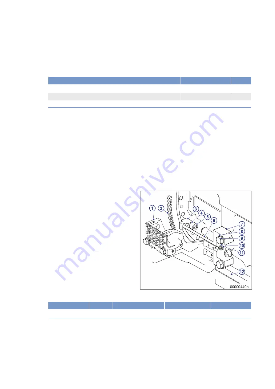
Removing the transport locking
device from driving end (KS)
1.
Release nut (11) on both sides.
2.
Remove screw (5), washer (4), holder (3) and
screw (6) from flywheel (2).
3.
Remove screw (9), washer (8) and holder (7)
from crankcase (12).
4.
Install the two screws with washers to secure the diaphragm coupling to the flywheel.
Name
Size
Type
Lubricant
Value/Standard
Screw
Tightening torque
250Nm +25 Nm
Installing the transport locking device on driving end (KS)
1.
Remove the transport locking device installed by MTU (→ Page 19).
2.
Remove protective cover from flywheel housing (1).
22 | Transport | MS150049/04E 2017-04
TIM-ID: 0000040576 - 001


