LambdaDriver 400 & 800
ML46430, Rev. 07
October 2004
Right LDx00s
Same as for left LDx00s.
Cabling
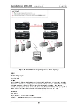
LDx00 (B) to LDx00 (B) Cabling
With Service Modules: As in Figure 53.
Without Service Modules: As in Figure 43.
LDx00 (A) to LDx00 (B) Cabling
ESCON-to-Transponder: With the aid of
nterconnect the ESCON Multiplexer modules
in LDx00 (
A
) and the Transponder modules in LDx00 (
B
), making sure that modules in slots of
the same number are interconnected
.
Intra-LDx00 Cabling
LDx00 (A): None.
LDx00 (B):
With
Service and Management Modules:
Transponder-to-Mux: As in Figure 55.
Demux-to-Transponder: As in Figure 56
Mux-to-Service: As in Figure 58.
Service-to-Demux: As in Figure 58.
Management-to-Service: As in Figure 60.
Without
Service Module:
Simply skip connections for the Service module described just above. This means that the
OUT
ports of the Muxes are directly connected to the
IN
ports of the Demuxes, as shown in
Without
Management Module:
Simply skip connections for the Management Module.
LDx00 to RS-232/Ethernet Cabling
LDx00-to-RS-232: As shown in Figure 78.
LDx00-to-Ethernet: As shown in Figure 79.
Data Flow
Left LDx00s
ESCON Multiplexer modules 1 to 8 transmit to Transponder modules 1 to 8. The Transponder
modules send the data to the Mux Module which multiplexes the data and drives it on the fiber
connected to its OUT port towards the remote LDx00 (B).
The data received at the remote LDx00 (B) enters the IN port of the Demux Module which
demultiplexes the data to the transponder modules. The transponder modules drive the data to
the ESCON Multiplexer modules, which send the data to the ESCON lines.
Right LDx00s
Same as for left LDx00s.
90


