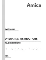
Undercounter T
emperature Display Board
P/N 0512106
-1
B
Rinse T
est
Pushbutton
A
W
ire Har
ness Plug
for W
ash and Rinse
Ther
mistors
C
W
ash T
est
Pushbutton
D
Booster
Temperature
Adjust
M4
SETTING
ONL
Y
E
W
ash
Temperature
Adjust
M4
SETTING
ONL
Y
Diagnostics
A -
When testing the circuit board
operation, disconnect the har
n-
ess from this plug. The wash and
rinse displays will display E.
B -
Push and hold the rinse test
pushbutton. A numerical value
of 179-180 should appear
in the rinse temperature display
window indicating the circuit
board is operating nor
mally
.
C -
Push and hold the wash test
pushbutton for 10 seconds
A numerical value of 140
should appear in the wash
temperature display window
indicating the circuit board
is operating nor
mally
.
When per
for
ming diagnostics the values are
displayed in °F even if the display is set for °C.
A F/C Slide switch is provided on the board
to change the display from the factor
y default
setting of °F to the optional °C.
D -
Tur
n clockwise to increase the
booster temperature. Full range
is 3/4 tur
ns 180-200°F
. DO
NOT FORCE P
AST THE STOPS.
E -
Tur
n clockwise to increase the
wash temperature. Full range is
3/4 tur
ns 120-160°F
. DO NOT
FORCE P
AST THE STOPS.
Temperature Adjustments
Digital Temperature Display Board - 201HT, 201LT
66
Summary of Contents for 201HT M4 Series
Page 26: ...Blank Page This Page Intentionally Left Blank 18...
Page 39: ...This Page Intentionally Left Blank Blank Page 31...
Page 44: ...Blank Page This Page Intentionally Left Blank 36...
Page 64: ...This Page Intentionally Left Blank Blank Page 56...
Page 70: ...Timer Board Connection Diagram 201HT 201LT 62...
Page 76: ...Blank Page This Page Intentionally Left Blank 68...
Page 77: ...Models 201HT 201LT Service Replacement Parts 201HT 201LT Service Replacement Parts 69...
Page 78: ...This Page Intentionally Left Blank Blank Page 70...
Page 80: ...72 Wash Pump Motor Assembly 201HT 201LT 1 11 12 2 3 4 5 7 8 9 10 6 13 14 15...
Page 85: ...Blank Page This Page Intentionally Left Blank 77...
Page 88: ...80 Fill Solenoid Valve 201HT 201LT 1 2 3 4 9 5 6 7 8...
Page 96: ...88 Booster Assembly 201HT Only 1 1 2 2 3 4 1 6 5 7 8 9 10 11 12 13 4 15 14...
Page 104: ...96 Control Panel 201HT Only 1 2 2 3 6 5 7 5 10 8 8 9 9 11 10 4...
Page 108: ...100 Panels 201HT 201LT 6 1 3 2 4 5 7 9 8 8...
Page 110: ...102 Door Assembly 201HT 201LT 1 4 5 6 6 7 7 9 9 8 2 3 3 5 10 10...
Page 112: ...104 Dish Racks Line Strainer PRV 201HT 201LT 1 2...
Page 114: ...This Page Intentionally Left Blank Blank Page 106...
Page 116: ...Electrical Schematic 201HT Only 108 SINGLE PHASE THREE PHASE 4 AMP FUSE 201HT...
Page 118: ...110 Timing Charts 201HT 201LT 201HT 201LT UL130...
Page 119: ......
Page 120: ......