


PTP 250 User Guide
Testing link end hardware
phn-2182_002v000
May 2011
8-7
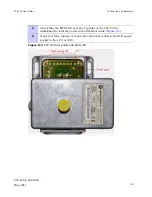
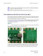
5
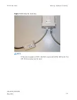
Check that the PWR LED near the top right of the LPU PCB is
illuminated to indicate power in the Ethernet cable (
Figure 8-3
).
6
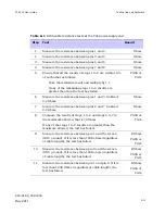
If any test fails, replace or repair the cable that connects the PoE power
supply to the LPU or ODU.
Figure 8-3
PTP LPU test points and PWR LED
Summary of Contents for Motorola PTP 250
Page 20: ...List of Tables phn 2182_002v000 xiv May 2011 ...
Page 30: ......
Page 80: ...Data network planning Chapter 2 Planning considerations phn 2182_002v000 2 22 May 2011 ...
Page 126: ...Notifications Chapter 4 Reference information phn 2182_002v000 4 36 May 2011 ...
Page 234: ...Testing the radio link Chapter 8 Troubleshooting phn 2182_002v000 8 14 May 2011 ...