


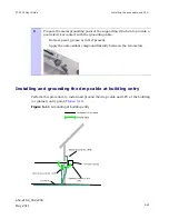


Installing the drop cable and LPU
Chapter 5 Installation
phn-2182_002v000
5-16
May 2011
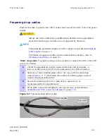
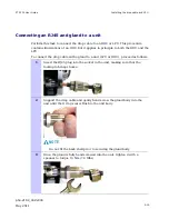
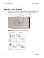
‘LPU-PoE’ cable
: To prepare a short section of cable to connect the LPU to the PoE
power supply, proceed as follows:
1
Cut off the approximate length required (allowing a bit of surplus).
2
Fit an RJ45 connector and gland to the top end only, as described in
Assembling an RJ45 connector and gland
on page
5-16
.
Assembling an RJ45 connector and gland
Perform this task to prepare the outdoor CAT5e cable with connectors and glands.
Safety precautions
WARNING
The metal screen of the drop cable is very sharp and may cause
personal injury.
When preparing the drop cable, take the following safety precautions:
x
ALWAYS wear cut resistant gloves (check the label to ensure they are cut
resistant).
x
ALWAYS wear protective eyewear.
x
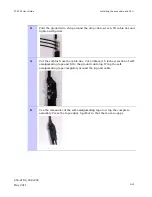
ALWAYS use a rotary blade tool to strip the cable (DO NOT use a bladed knife).
To use the rotary blade tool, fit it around the outer cable sheath and rotate the
cutter around the cable once or twice. The stripped outer section can then be
removed.
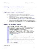
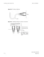
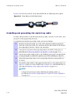
Assembly
Assemble the drop cable as shown in
Figure 5-8
. The gland is only required for outdoor
connections at the ODU or LPU. The connection to the PoE power supply requires the
RJ45 plug but no gland.
Summary of Contents for Motorola PTP 250
Page 20: ...List of Tables phn 2182_002v000 xiv May 2011 ...
Page 30: ......
Page 80: ...Data network planning Chapter 2 Planning considerations phn 2182_002v000 2 22 May 2011 ...
Page 126: ...Notifications Chapter 4 Reference information phn 2182_002v000 4 36 May 2011 ...
Page 234: ...Testing the radio link Chapter 8 Troubleshooting phn 2182_002v000 8 14 May 2011 ...