


Testing link end hardware
Chapter 8 Troubleshooting
phn-2182_002v000
8-2
May 2011
Testing link end hardware
This section describes how to test the link end hardware, either when it fails on
startup, or after a lightning strike.
Before testing link end hardware, confirm that all outdoor drop cables, that is those
that connect the ODU to equipment inside the building, are of the supported type, as
defined in
Installation inventories
on page
4-2
.
NOTE
These tests apply to installations that use the PoE power supply. If the PIDU
is installed instead of the PoE power supply, the test procedures will be
different.
Testing when PoE LEDs do not illuminate correctly
If the DATA & POWER OUT and DATA IN LEDs do not illuminate correctly during the
start-up sequence, test the link end as described in
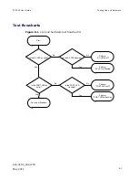
Test flowcharts
on page
8-3
and
the detailed test procedures that follow.
Testing after a lightning strike
If the installation has been struck by lightning, proceed as follows:
1
Test the link end as described in
Test flowcharts
on page
8-3
and the
detailed test procedures that follow.
2
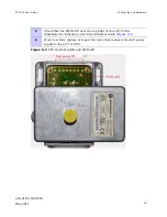
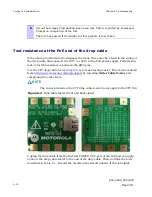
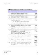
Ensure that the PoE power supply is working and that the resistances
are correct as specified in
Test resistance at the PoE end of the drop
cable
on page
8-10
.
3
If the ODU is not working, power off the ODU and LPU and return them
to Motorola.
4
If the ODU is working but there is suspicion of damage to the LPU, then
refer to
LPU Operational Troubleshooting (phn-1362).
Summary of Contents for Motorola PTP 250
Page 20: ...List of Tables phn 2182_002v000 xiv May 2011 ...
Page 30: ......
Page 80: ...Data network planning Chapter 2 Planning considerations phn 2182_002v000 2 22 May 2011 ...
Page 126: ...Notifications Chapter 4 Reference information phn 2182_002v000 4 36 May 2011 ...
Page 234: ...Testing the radio link Chapter 8 Troubleshooting phn 2182_002v000 8 14 May 2011 ...