


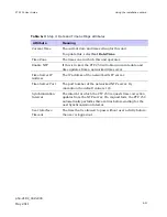


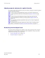


Aligning antennas
Chapter 6 Configuration and alignment
phn-2182_002v000
6-26
May 2011
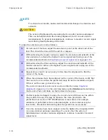
NOTE
To achieve best results, make small incremental changes to elevation and
azimuth.
CAUTION
The action of tightening the mounting bolts can alter antenna alignment.
This can be helpful when fine-tuning alignment, but it can also lead to
misalignment. To prevent misalignment, continue to monitor receive signal
level during final tightening of the bolts.
To align the antennas, proceed as follows:
1
At each end of the link, adjust the antenna to point at the other end of the
link. This should be done with the aid of a compass.
2
Without moving the master antenna, adjust the elevation and azimuth of the
slave antenna to achieve the highest receive signal level (using one of the
recommended methods in
Monitoring received signal level
on page
6-27
).
3
Without moving the Slave antenna, adjust the elevation and azimuth of the
Master antenna to achieve the highest receive signal level (using one of the
recommended methods).
4
Repeat steps 2 and 3 as necessary to fine-tune the alignment to find the
center of the beam.
5
When the antennas have been aligned on the center of the beam, verify that
the receive level is within the predicted range (from the installation report).
If this is not the case, go back to step 2.
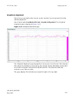
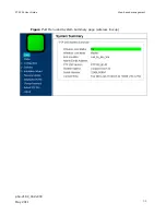
The current value of receive level can be verified by using
Graphical
alignment
on page
6-29
or by selecting menu option
Status
and monitoring
the Receive Power attribute on the System Status page.
6
If after repeated attempts to align, the receive level still does not lie within
the predicted range, this may be because the data provided to the
prediction tool (such as PTP LINKPlanner) is inaccurate. For example
estimates of path obstructions, antenna heights or site locations may be
inaccurate. Check this data and update the prediction as necessary.
7
Once the antennas have been aligned correctly,
t
ighten the integrated ODU
(or connectorized antenna) mountings. To ensure that the action of
tightening does not alter antenna alignment, continue to monitor received
signal level.
Summary of Contents for Motorola PTP 250
Page 20: ...List of Tables phn 2182_002v000 xiv May 2011 ...
Page 30: ......
Page 80: ...Data network planning Chapter 2 Planning considerations phn 2182_002v000 2 22 May 2011 ...
Page 126: ...Notifications Chapter 4 Reference information phn 2182_002v000 4 36 May 2011 ...
Page 234: ...Testing the radio link Chapter 8 Troubleshooting phn 2182_002v000 8 14 May 2011 ...