General Command and Response Message Types
Moog Animatics Class 6 EtherNet/IP Guide, Rev. B
Page 47 of 160
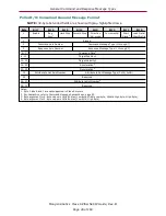
Polled I/O: Produced General Message Format
NOTE:
32-byte Extended fields are shown with gray-highlighted rows.
Byte
Bit 7
Bit 6
Bit 5
Bit 4
Bit 3
Bit 2
Bit 1
Bit 0
0
Enable
Reg.
Level
1
Home
Level
1
Current
Direction
General
Fault
On Target
Position
Block in
Execution
1
Profile in
Progress
1
Block #
2
Load
Complete
Block
Fault
1
Following
Error Fault
Negative
Limit
Positive
Limit
Reverse
Limit
Forward
Limit
Fault
Input
1,2
3
Response Axis Number
Response Message Type (1 through 5)
4–7
Response Data
4
8–11
Actual Position
4
12–15
Actual Velocity
4
16–19
Reserved
20
Attribute to Get Axis Number
Attribute to Get Message Type (0x1A, 0x1B)
21
Reserved
22–23
Attribute to Get Number
5
24–27
Attribute to Get Data
No data if Attribute to Get Axis Number and Message Type are zero
28–31
Reserved
Notes:
1. Not supported.
2. Byte 2 bit 0 can be configured as the Servo Bus Voltage Okay status.
3. For semantics, refer to Response Message Semantics on page 53.
4. Byte alignment for 4-byte values is Little Endian (Low byte, Middle Low byte, Middle High byte, High Byte).
5. Byte alignment for 2-byte values is Little Endian (Low byte, High Byte).
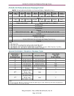
General Command / Response Message Types
Command /
Response
Message Type
Command Data
Response Data
Class 0x25
Attr #3
Mode Setting
1
a
Target Position
Actual Position
0
2
a
Target Velocity
Command Position
1
3
Acceleration
Actual Velocity
N/A
4
Deceleration
Command Velocity
N/A
5
a
Torque
Torque
2
6
a,b
Position Profile
Move - See
description below
N/A
0
7
a,b
Velocity Profile
Move - See
description below
N/A
1
Notes:
a. The drive Control Mode must match the desired command type in order to start a profile move or apply torque.
b. Only available for 32-byte connections.


