


10
- Affix the adhesive tab indicating the new type of
gas used.
- The nozzles and adhesive tabs are supplied with
the appliance.
REPLACING THE NOZZLE AND THE MAIN BURNER
PRIMARY AIR REGULATION
- Slacken screw V.
- Remove nozzle UM (fitted to air regulator Z) and
replace it with the one indicated in table TAB1.
- Retighten nozzle UM (fitted to air regulator Z).
- Adjust air regulator Z to distance A as shown in
table TAB1.
- Retighten screw V fully.
- Reassemble all parts. For assembly, proceed in
reverse order.
REPLACING THE PILOT BURNER NOZZLE
- Remove the front panel.
- Open the door.
- Undo connector R.
- Remove nozzle UP and replace it with the one
indicated in table TAB1.
- Retighten connector R. Reassemble all parts.
- Following, in reverse order, the sequence used
for their removal.
9.
COMMISSIONING
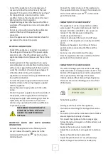
Following installation, conversion to a different
type of gas or any maintenance operations, check
appliance operation. In the event of any
malfunction, consult the next Paragraph "
Troubleshooting " .
GAS APPLIANCES
- Switch on the appliance as directed in the
instructions and reminders for use given in
Chapter “ INSTRUCTIONS FOR USE “ and check:
- the gas supply pressure (see next Paragraph).
- the correct ignition of the burners and the
effectiveness of the fumes removal system.
CHECKING THE GAS SUPPLY PRESSURE
- To measure the gas supply pressure use a
manometer with a minimum definition of 0,1
mbar.
- Remove the control panel.
- Remove the screw from on pressure test point PP
and connect the manometer to the test point.
- Make the measurement with the appliance in
operation.
IMPORTANT! IF THE GAS SUPPLY
PRESSURE IS NOT WITHIN THE LIMITS
(MIN. - MAX) INDICATED IN TABLE
TAB2, CEASE OPERATION OF THE
APPLIANCE AND CONTACT THE GAS
UTILITY COMPANY.
Disconnect the manometer and retighten the
retaining screw on the pressure connection.
ELECTRIC EQUIPMENT
Switch on the appliance as directed in the
instructions and reminders for use given in
Chapter “ INSTRUCTIONS FOR USE “ and check:
the current values of each phase.
the correct operation of the heating elements.
III.
INSTRUCTIONS FOR USE
10.
REMINDERS FOR THE USER
READ THIS MANUAL CAREFULLY. IT
PROVIDES IMPORTANT INFORMATION
FOR SAFE INSTALLATION, USE AND
MAINTENANCE OF THE APPLIANCE.
THE MANUFACTURER WILL NOT BE
LIABLE FOR ANY DAMAGE OR INJURY
RESULTING FROM FAILURE TO
OBSERVING THE FOLLOWING RULES.
For after-sales service, contact technical
assistance centres authorized by the
manufacturer and demand the use of original
spare parts.
Have the appliance serviced at least twice a year.
The manufacturer recommends taking out a
service contract.
The appliance is designed for professional use
and must be operated by trained personnel.
The appliance is to be used for cooking food as
specified in the prescriptions for use. Any other
use is considered to be improper.
Do not allow the appliance to operate empty for
prolonged periods. Only pre-heat the oven just
before use.
Do not leave the appliance unattended while in
operation.
Summary of Contents for FU 110/40 FRGS13 PW
Page 29: ...29 RU I...
Page 30: ...30 1 PE PP 90...
Page 31: ...31 2 II 3 4 5...
Page 32: ...32 6 10 A1 A1 B21 B21 B11 B11 150 155 300 C 3 2 3 7...
Page 33: ...33 III H05 RN F 150 300 o 100 C 8 TAB1 TAB1 TAB1...
Page 34: ...34 UM A UP Um V UM Z TAB1 UM Z Z A TAB1 V R UP TAB1 R 9 0 1 PP TAB2 III 10...
Page 35: ...35 11...
Page 36: ...36 600 650 H...
Page 37: ...37 10 15 POWER...
Page 38: ...38 10 15 0 12 60 IV 13...
Page 39: ...39 V 14 15 16 17...
Page 40: ...40 18 V UM Z TAB1 UM Z Z A TAB1...
Page 41: ...41 V 19 20...
Page 113: ...113...
Page 114: ...114...
Page 115: ...115...
Page 116: ...116...
Page 117: ...117...
Page 118: ...118...
Page 119: ...119...
Page 120: ...120...
Page 121: ...121...
Page 122: ...122...
Page 123: ...123...
Page 124: ...124...
Page 125: ...125...
Page 126: ...126 VII FIG IMAGE RYSUNKI FIGURER FIGURER BR K FIGURI...
Page 127: ...127...