background image

5 - 8                                                                                                                                                       5 - 8

MELSEC-Q

5   UTILITY PACKAGE (GX Configurator-AD)

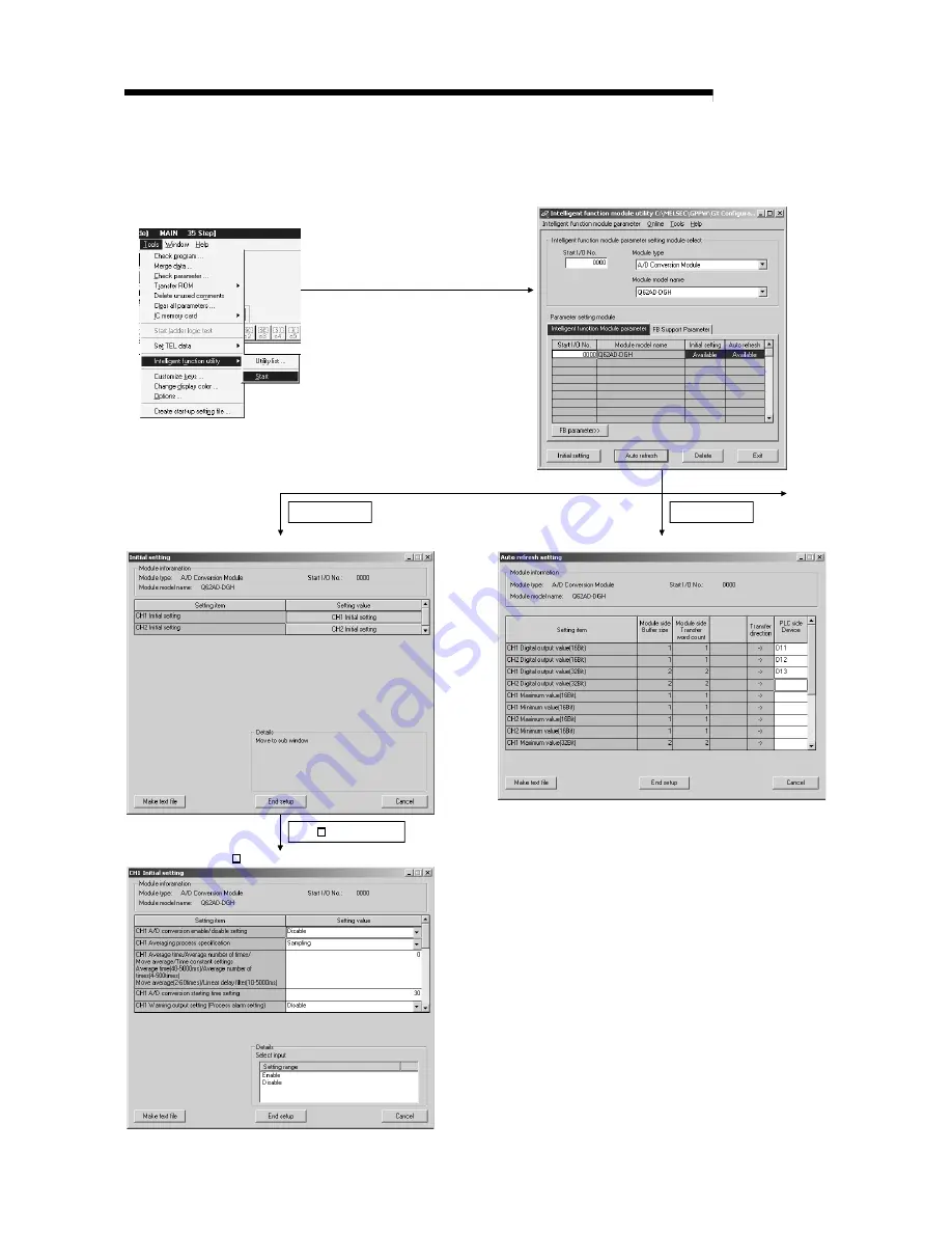
5.3.2 Operation overview

See Section 5.3.3

GX Developer screen

1)

setting module select screen

Initial setting screen

Initial setting

Auto refresh

Auto refresh setting screen

See Section 5.4

See Section 5.4

See Section 5.5

[Tools] – [Intelligent function utility]– [Start]

CH    Initial setting

CH    Initial setting screen

Intilligent function module parameter 

Summary of Contents for GX Configurator-AD

Page 1: ...odule With Signal Conditioning Function User s Manual U User s Manual Mitsubishi Programmable Logic Controller Q64AD GH Q62AD DGH GX Configurator AD SW2D5C QADU E Channel Isolated High Resolution Analog Digital Converter Module Channel Isolated High Resolution Analog Digital Converter Module With Signal Conditioning Function ...

Page 2: ......

Page 3: ...jury or physical damage Note that the CAUTION level may lead to a serious consequence according to the circumstances Always follow the instructions of both levels because they are important to personal safety Please store this manual in a safe place and make it accessible when required Always forward it to the end user DESIGN PRECAUTION DANGER Do not write data into the system area of the buffer m...

Page 4: ...re some restrictions on replaceable modules and the replacement procedures are predetermined for each module For details refer to the chapter of the online module change in this manual Do not directly touch the conductive area or electronic components of the module Doing so may cause malfunction or failure in the module WIRING PRECAUTIONS CAUTION Always ground the FG terminal of the Q62AD DGH Not ...

Page 5: ...from the base unit more than 50 times IEC 61131 2 compliant after the first use of the product Failure to do so may cause malfunction Do not touch the connector while the power is on Doing so may cause malfunction Be sure to shut off all phases of the external power supply before cleaning or retightening the terminal screws or module fixing screws Not doing so may cause failure or malfunction of t...

Page 6: ... Section 5 6 3 5 7 5 8 Correction Section 1 1 5 1 5 2 1 5 2 2 5 3 1 5 3 2 5 3 3 5 6 1 5 6 2 Appendix 1 3 Oct 2004 SH NA 080277 F Correction SAFETY PRECAUTIONS Section 2 1 3 1 1 4 1 6 3 6 5 1 Sep 2005 SH NA 080277 G Correction SAFETY PRECAUTIONS Section 2 1 3 1 1 5 2 2 6 3 2 Feb 2006 SH NA 080277 H Correction Section 2 2 6 2 1 6 2 2 6 3 1 6 3 2 6 4 1 6 4 2 6 5 1 6 5 2 Appendix1 Japanese Manual Vers...

Page 7: ...for Power Supply from Q61P A1 A2 to Q64AD GH 2 5 3 SPECIFICATIONS 3 1 to 3 49 3 1 Performance Specifications 3 1 3 1 1 Performance specifications list 3 1 3 1 2 I O conversion characteristic 3 4 3 1 3 Accuracy 3 9 3 2 Function List 3 10 3 2 1 A D conversion methods 3 11 3 2 2 Maximum and minimum values hold function 3 13 3 2 3 Input signal error detection function 3 13 3 2 4 Warning output functio...

Page 8: ...4 3 4 18 CH rate alarm warning detection period buffer memory addresses 118 to 121 Un G118 to Un G121 3 45 3 4 19 CH rate alarm upper lower limit value buffer memory addresses 122 to 137 Un G122 to Un G137 3 46 3 4 20 CH input signal error detection setting value buffer memory addresses 138 to 141 Un G138 to Un G141 3 47 3 4 21 Mode switching setting buffer memory addresses 158 159 Un G158 Un G159...

Page 9: ... Using the Utility Package 6 9 6 3 2 Programming Example without Using the Utility Package 6 12 6 4 For Use in Normal System Configuration Q62AD DGH 6 15 6 4 1 Programming Example Using the Utility Package 6 16 6 4 2 Programming Example without Using the Utility Package 6 18 6 5 For Use in Remote I O Network Q62AD DGH 6 19 6 5 1 Programming Example Using the Utility Package 6 20 6 5 2 Programming ...

Page 10: ... 8 3 8 2 3 When the ALM LED is on or flashing 8 3 8 2 4 When the digital output values cannot be read 8 4 8 2 5 When A D conversion completed flag does not turn ON during use in normal mode 8 5 8 2 6 Checking the A D converter module status using GX Developer system monitor 8 5 APPENDIX App 1 to App 14 Appendix 1 Dedicated Instruction List and Available Devices App 1 Appendix 1 1 OFFGAN App 2 Appe...

Page 11: ...eveloper to create a program and print out monitor and debug the program Sold separately SH 080373E 13JU41 GX Developer Version 8 Operating Manual Function Block Describes the methods of using GX Developer to create a function block and print out the function block Sold separately SH 080376E 13JU44 REMARK If you would like to obtain a manual individually printed matters are available separately Or...

Page 12: ...s refer to Chapter 3 EMC Directives and Low Voltage Directives of the User s Manual Hardware included with the CPU module or base unit used The CE logo is printed on the rating plate on the main body of the PLC that conforms to the EMC directive and low voltage instruction By making this product conform to the EMC directive and low voltage instruction it is not necessary to make those steps indivi...

Page 13: ...s SWnD5C GPPW E SWnD5C GPPW EA SWnD5C GPPW EV and SWnD5C GPPW EVA n in the model name is 4 or greater GX Configurator AD Generic term for analog digital converter module setting and monitor tool GX Configurator AD SW2D5C QADU E QCPU Q mode Generic term for Q00JCPU Q00CPU Q01CPU Q02CPU Q02HCPU Q06HCPU Q12HCPU Q25HCPU Q12PHCPU Q25PHCPU QnPHCPU Generic term for Q12PHCPU and Q25PHCPU Personal computer...

Page 14: ...AD GH Channel Isolated High Resolution Analog Digital Converter Module 1 Q62AD DGH Type Q62AD DGH Channel Isolated High Resolution Analog Digital Converter Module with Signal Conditioning Function 1 SW2D5C QADU E GX Configurator AD Version 2 1 license product CD ROM 1 SW2D5C QADU EA GX Configurator AD Version 2 Multiple license product CD ROM 1 ...

Page 15: ...2 wire transmitter Q62AD DGH only Supplying power to the 2 wire transmitter the Q62AD DGH does not require the power supply for the 2 wire transmitter Supply power can be switched ON OFF channel by channel by the A D conversion enable disable setting 4 Module protection provided by short circuit protection circuit Q62AD DGH only If an excessive current flows into the module due to a short circuit ...

Page 16: ...fied number of digital output values measured per sampling time are averaged c Primary delay filter A digital output value is smoothed according to the preset time constant 9 Input signal error detection function The voltage current outside the setting range is detected 10 Warning output There are the following two warning outputs a Process alarm A warning is output if a digital output value falls...

Page 17: ... of the intelligent function module parameters initial setting auto refresh setting In addition FB 1 can be generated automatically from the intelligent function module parameters that have been set up and used in a sequence program 1 FB is the function for making a circuit block used in a sequence program repeatedly a part FB to use it in the sequence program This function can improve the efficie...

Page 18: ...o use 2 See Q Corresponding MELSECNET H Network System Reference Manual Remote I O network 2 Base Unit in which the converter module can be installed The A D converter module can be installed in any I O slot 3 of the base unit However a power shortage may occur depending on the combination with other installed modules and the number of modules used so always take into consideration the power suppl...

Page 19: ...on 4 or later Q02 Q02H Q06H Q12H Q25HCPU Multiple PLC system Version 6 or later Single PLC system Q12PH Q25PHCPU Multiple PLC system Version 7 10L or later If installed in a MELSECNET H remote I O station Version 6 or later Version 1 14Q or later 4 When using the pass data use the product of Version 1 16S or later 6 Q62AD DGH compatible software packages The following table indicates the compatibi...

Page 20: ...g the SERIAL column of the rating plate located on the side of the module Function version Conformed standard Serial No First 6 digits b To check the function version and product information using GX Developer Refer to Section 8 2 6 of this manual POINT The serial No described on the rated plate may not match with the serial No displayed on the product information of GX Developer The serial No on ...

Page 21: ...Product information screen Startup procedure GX Developer Help Product information In the case of GX Developer Version 7 Software version REMARK The version indication for the GX Configurator AD has been changed as shown below from the SW0D5C QADU E 50F upgrade product Previous product Upgrade and subsequent versions SW0D5C QADU E 50F GX Configurator AD Version 1 10L ...

Page 22: ... unit Table 2 1 Conditions for Use of Q61P A1 A2 and Q64AD GH in Combination Available power supply No of Q64AD GH modules Conditions Q61P A1 A2 Q64P Total current consumption of all modules on the same base is 5 0A or less 3 or less Total current consumption of all modules on the same base exceeds 5 0A Module other than the Q64AD GH is not mounted on the same base 4 Module other than the Q64AD GH...

Page 23: ...2 6 2 6 MELSEC Q 2 SYSTEM CONFIGURATION MEMO ...

Page 24: ...ut value 32 bit 32digit 2 Digital output value 16 bit 16digit 2 Accuracy Accuracy relative to digital output value Temperature coefficient 3 71 4ppm C 0 00714 C Common mode voltage Input Common ground input voltage 0V 1780VAC Common mode characteristic Common mode voltage rejection ratio VCM 1780V 60Hz 105dB 50Hz 107dB Conversion speed 10ms 4 channels Absolute maximum input Voltage 15V Current 30m...

Page 25: ... area Isolation method Dielectric withstand voltage Insulation resistance Between I O terminal and PLC power supply Photocoupler isolation Between analog input channels Transformer isolation Between external supply power and analog input Transformer isolation 1780VAC rms 3 cycles elevation 2000m 500VDC 10M or more Isolation specifications Maximum number of writes for E2 PROM 100 000 Number of I O ...

Page 26: ...3 3 3 3 MELSEC Q 3 SPECIFICATIONS REMARK See the user s manual for the CPU module being used for general specifications of the A D converter modules ...

Page 27: ...ue and gain value when the analog signals voltage or current input from outside the PLC are converted to digital values Offset value The offset value denotes the analog input value voltage or current that makes the digital output value 0 Gain value The gain value denotes the analog input value voltage or current that makes the digital output value 32000 16 bits 64000 32 bits ...

Page 28: ...es indicates the digital output value 16 bits Maximum resolution Number Analog input range setting Offset value Gain value Digital output value 32 bits 2 Digital output value 16 bits 2 32 bits 16 bits 1 1 to 5V 1V 5V 62 5µV 125 0µV 2 0 to 5V 0V 5V 0 to 64000 0 to 32000 78 2µV 156 4µV 3 10 to 10V 0V 10V 64000 to 64000 32000 to 32000 4 0 to 10V 0V 10V 156 3µV 312 6µV User range setting Uni polar 1 1...

Page 29: ... for the user setting range 1 within a range in which the following conditions are satisfied a Offset value gain value setting range 10V to 10V b gain value offset value 3 030V 4 When an analog value that exceeds the range for the digital output value 2 is entered the digital output value will be fixed at the maximum or minimum value Digital output value 32 bits Digital output value 16 bits Analog...

Page 30: ...OINT 1 Set within the analog input range and digital output range for each input range If these ranges are exceeded the maximum resolution and accuracy may not fall within the performance specifications Avoid use in the dotted area of Fig 3 2 2 Do not input an analog input current of more than 30 mA A breakdown may result due to overheating 3 Set the offset gain values for the user setting range 1...

Page 31: ...3 Input characteristic of Q62AD DGH POINT 1 Set within the analog input range and digital output range for each input range If these ranges are exceeded the maximum resolution and accuracy may not fall within the performance specifications Avoid use in the dotted area of Fig 3 3 2 Set the offset gain values for the user setting range 1 within a range in which the following conditions are satisfied...

Page 32: ...ccuracy relative to the maximum value of the digital output value If you change the offset gain setting or input range to change the input characteristic the reference accuracy and temperature coefficient do not vary and kept within the ranges given in the performance specifications Example Accuracy when the temperature varies from 25 C to 30 C 0 05 reference accuracy 0 00714 C temperature coeffic...

Page 33: ...put value is smoothed according to the preset time constant Section 3 2 1 Maximum and minimum values hold function 1 The maximum and minimum values of the digital output values is retained in the module Section 3 2 2 Input signal error detection function 1 The voltage current outside the setting range is detected Section 3 2 3 Warning output function 1 Process alarm A warning is output if a digita...

Page 34: ...umber of times the sum of values other than the maximum and minimum values is averaged and the result is stored into the buffer memory The time when the count based average value is stored into the buffer memory is uniform independently of the number of used channels number of channels set for A D conversion enable Processing time set count 10 ms Example When the averaging processing count is set ...

Page 35: ...digital output value at the time constant setting of 1000ms 1s is as shown below 1000ms 1s after the analog input value has reached 1V the digital output value reaches 63 2 of the value attained when the sampling processing is selected 0 1000 0 0 2 0 4 0 6 0 8 1 1 2 12000 10000 0 2000 4000 6000 8000 Analog input value Digital output value Elapsed time ms Digital output value Analog input value V E...

Page 36: ...put signal error detection flag buffer memory address 49 Un G49 turned ON is held as immediately before detection of the error and the A D conversion completed flag buffer memory address 10 Un G10 of the corresponding channel turns OFF 3 By bringing the analog input value within the setting range and then turning ON the error clear request YF the input signal error detection flag buffer memory add...

Page 37: ...larm lower upper limit value and returned to within the setting range 0 is stored into the bit position corresponding to the channel number of the warning output flag buffer memory address 48 Un G48 The warning output signal X8 turns OFF only when all channels return to within the setting range Digital output value Upper upper limit value Upper lower limit value CH1 digital output value Lower uppe...

Page 38: ...nd returned to within the setting range 0 is stored into the bit position corresponding to the channel number of the warning output flag buffer memory address 48 Un G48 The warning output signal X8 turns OFF only when all channels return to within the setting range Digital output value Rate alarm warning detection period CH1 digital output value CH2 digital output value Time Varying rate of digita...

Page 39: ...judgment per rate alarm warning detection period digit rate alarm upper limit value or lower limit value 0 001 64000 rate alarm warning detection period 1000 Example When the varying rate upper limit value of channel 1 is set to 30 s 300 is stored into the buffer memory and the rate alarm warning detection period of channel 1 is 10ms the current and previous values are compared at intervals of 10m...

Page 40: ...ied range 30 20 0 Varying rate of digital output value Rate alarm upper limit value Rate alarm lower limit value Time 3 Example of setting the rate alarm upper limit value lower limit value when it is desired to watch that the digital output value is at the varying rate within the specified range 10 10 0 Varying rate of digital output value Rate alarm upper limit value Rate alarm lower limit value...

Page 41: ...ransmitter powers on until its output stabilizes and the warm up time of the 2 wire transmitter ON ON Example When the time necessary from when the 2 wire transmitter powers on until its output stabilizes is 500ms A D conversion enable disable setting Power supply to 2 wire transmitter ON OFF Buffer memory address 0 Un G0 26V power supply to 2 wire transmitter Analog output of 2 wire transmitter A...

Page 42: ...Y3 X4 Y4 X5 Y5 X6 Y6 X7 Use prohibited 1 Y7 X8 Warning output signal Y8 Use prohibited 1 X9 Operating condition setting completed flag Y9 Operating condition setting request XA Offset gain setting mode flag YA User range writing request XB Channel change completed flag YB Channel change request XC Input signal error detection signal YC Use prohibited 1 XD Maximum value minimum value reset complete...

Page 43: ...st XA Offset gain setting mode flag YA User range writing request XB Channel change completed flag YB Channel change request Input signal error detection signal XC Offset gain change completed flag YC Offset gain change request XD Maximum value minimum value reset completed flag YD Maximum value minimum value reset request XE A D conversion completed flag YE Use prohibited 1 XF Error flag YF Error...

Page 44: ...unction has been made valid 2 As soon as the digital output values return to within the setting ranges on all channels enabled for A D conversion this signal turns OFF automatically and the ALM LED is also extinguished b Rate alarm 1 This signal turns ON when the varying rate of the digital output value falls outside the varying rate range set to the rate alarm upper lower limit values buffer memo...

Page 45: ...uffer memory address 47 Un G47 CH process alarm upper lower limit value buffer memory addresses 86 to 117 Un G86 to Un G117 CH rate alarm warning detection period buffer memory addresses 118 to 121 Un G118 to Un G121 CH rate alarm upper lower limit value buffer memory addresses 122 to 137 Un G122 to Un G137 CH input signal error detection setting value buffer memory addresses 138 to 141 Un G138 to...

Page 46: ...odule ready X0 Offset gain setting mode flag XA User range writing request YA Performed by the A D converter module Performed by the sequence program XA Offset gain setting mode flag In normal mode 1 This signal is used as an interlock condition to turn ON OFF the User range writing request YA when the user range is restored 2 Refer to Chapter 7 for the user range restoration ON Performed by the A...

Page 47: ...signal error detection signal turns ON 1 The A D conversion completed flag buffer memory address 10 Un G10 of the corresponding channel turns OFF 2 The digital output value is held as at the time of error detection 3 The ALM LED flickers 3 By bringing the analog input value within the setting range and then turning ON the Error clear request YF the Input signal error detection signal XC turns OFF ...

Page 48: ...7 Un G62 to Un G77 Maximum value minimum value reset request YD Performed by the A D converter module Performed by the sequence program XE A D conversion completed flag 1 This turns ON when conversion for all of the channels that are conversion enabled has been completed 2 1 When the external supply power to the Q62AD DGH switches OFF the A D conversion completed flag turns OFF the digital output ...

Page 49: ...t gain setting mode 1 This turns ON when the value for the adjusted offset gain settings are registered in the A D converter module 2 See the XA column for ON OFF timing See Section 4 6 for offset gain settings YA User range writing request In normal mode 1 This signal turns ON when the user range is restored 2 Refer to the field of XA for the ON OFF timing Refer to Chapter 7 for user range restor...

Page 50: ...G10 Digital output value Buffer memory addresses 11 to 14 54 to 61 Un G11 to 14 Un G54 to 61 Power of 2 wire transmitter During restoration Restoration completed Power ON Power OFF Power ON During user range restoration A D conversion stop A D conversion completed flag buffer memory addresses 10 Un G10 OFF digital output value held as previously power of 2 wire transmitter OFF Q62AD DGH only After...

Page 51: ... 2 AH 10 A D conversion completed flag 0 R BH 11 CH1 Digital output value 16Bit 0 R CH 12 CH2 Digital output value 16Bit 0 R DH 13 CH3 Digital output value 16Bit 0 R EH 14 CH4 Digital output value 16Bit 0 R FH 15 to to 12H 18 System area 13H 19 Error code 0 R 14H 20 Setting range 0 R 15H 21 System area 16H 22 Offset gain setting mode offset specification 0 R W 17H 23 Offset gain setting mode gain ...

Page 52: ... 60 3DH 61 CH4 Digital output value 32Bit L H 0 R 3EH 62 3FH 63 CH1 Maximum value 32Bit L H 0 R W 2 40H 64 41H 65 CH1 Minimum value 32Bit L H 0 R W 2 42H 66 43H 67 CH2 Maximum value 32Bit L H 0 R W 2 44H 68 45H 69 CH2 Minimum value 32Bit L H 0 R W 2 46H 70 47H 71 CH3 Maximum value 32Bit L H 0 R W 2 48H 72 49H 73 CH3 Minimum value 32Bit L H 0 R W 2 4AH 74 4BH 75 CH4 Maximum value 32Bit L H 0 R W 2 ...

Page 53: ...R W 2 6CH 108 6DH 109 CH3 Process alarm upper upper limit value L H 0 R W 2 6EH 110 6FH 111 CH4 Process alarm lower lower limit value L H 0 R W 2 70H 112 71H 113 CH4 Process alarm lower upper limit value L H 0 R W 2 72H 114 73H 115 CH4 Process alarm upper lower limit value L H 0 R W 2 74H 116 75H 117 CH4 Process alarm upper upper limit value L H 0 R W 2 76H 118 CH1 Rate alarm warning detection per...

Page 54: ...a CAH 202 CBH 203 CH1 Industrial shipment settings offset value 3 L H 0 R W 2 CCH 204 CDH 205 CH1 Industrial shipment settings gain value 3 L H 0 R W 2 CEH 206 CFH 207 CH2 Industrial shipment settings offset value 3 L H 0 R W 2 D0H 208 D1H 209 CH2 Industrial shipment settings gain value 3 L H 0 R W 2 D2H 210 D3H 211 CH3 Industrial shipment settings offset value 3 L H 0 R W 2 D4H 212 D5H 213 CH3 In...

Page 55: ...ings gain value 3 L H 0 R W 2 E6H 230 E7H 231 CH4 User range settings offset value 3 L H 0 R W 2 E8H 232 E9H 233 CH4 User range settings gain value 3 L H 0 R W 2 1 Indicates whether reading and writing to from a sequence program are enabled R Read enabled W Write enabled 2 When writing data to the buffer memory always perform write under the interlock conditions buffer memory write conditions of t...

Page 56: ...0 Setting range 0 R 15H 21 System area 16H 22 Offset gain setting mode offset specification 0 R W 17H 23 Offset gain setting mode gain specification 0 R W 18H 24 to to 1DH 29 System area 1EH 30 CH1 Maximum value 16Bit 0 R W 2 1FH 31 CH1 Minimum value 16Bit 0 R W 2 20H 32 CH2 Maximum value 16Bit 0 R W 2 21H 33 CH2 Minimum value 16Bit 0 R W 2 22H 34 to to 2EH 46 System area 2FH 47 Input signal error...

Page 57: ...alue L H 0 R W 2 5EH 94 5FH 95 CH2 Process alarm lower lower limit value L H 0 R W 2 60H 96 61H 97 CH2 Process alarm lower upper limit value L H 0 R W 2 62H 98 63H 99 CH2 Process alarm upper lower limit value L H 0 R W 2 64H 100 65H 101 CH2 Process alarm upper upper limit value L H 0 R W 2 66H 102 to to 75H 117 System area 76H 118 CH1 Rate alarm warning detection period 0 R W 2 77H 119 CH2 Rate al...

Page 58: ...Industrial shipment settings offset value 3 L H 0 R W 2 D0H 208 D1H 209 CH2 Industrial shipment settings gain value 3 L H 0 R W 2 D2H 210 to to D9H 217 System area DAH 218 DBH 219 CH1 User range settings offset value 3 L H 0 R W 2 DCH 220 DDH 221 CH1 User range settings gain value 3 L H 0 R W 2 DEH 222 DFH 223 CH2 User range settings offset value 3 L H 0 R W 2 E0H 224 E1H 225 CH2 User range settin...

Page 59: ...4AD GH defaults to A D conversion enable on all channels 4 The Q62AD DGH defaults to A D conversion disable on all channels b15 b14 b13 b12 b11 b10 b9 b8 b7 b6 b5 b4 b3 b2 b1 b0 CH4 CH3 CH2 CH1 0 0 0 0 0 0 0 0 0 0 0 0 Q64AD GH For Q64AD GH information of b4 to b15 is fixed at 0 For Q62AD DGH information of b2 to b15 is fixed at 0 0 A D conversion enable 1 A D conversion disable Q62AD DGH 0 A D con...

Page 60: ...conversion processing is performed at the pre error setting 2 Since the default setting is 0 change it according to the processing method 3 The value which has been set to the channel specified for sampling processing is ignored 3 4 4 CH A D conversion starting time setting buffer memory addresses 5 6 Un G5 Un G6 Q62AD DGH only 1 This area is used to set the time necessary from when the used 2 wir...

Page 61: ...s b15 b12 b11 b8 b7 b4 b3 b0 to to to to CH4 CH3 CH2 CH1 For Q62AD DGH information of b8 to b15 is fixed at 0 Processing method Setting value Sampling processing 0H Time averaging 1H Count averaging 2H Move averaging 3H Primary delay filter 4H Example When setting channel 1 for count averaging channel 2 for time averaging channel 3 for primary delay filter and channel 4 for sampling processing sto...

Page 62: ... For Q64AD GH information of b4 to b15 is fixed at 0 For Q62AD DGH information of b2 to b15 is fixed at 0 1 A D conversion completed 0 A D conversion in progress or not used Example When all conversions of channels 1 and 2 enabled for A D conversion are completed 0003H 3 is stored into the buffer memory address 10 Un G10 b15 CH4 CH3 CH2 CH1 3 0 0 0003H 3 0 0 0 0 0 0 0 0 0 0 0 0 0 0 1 1 b14 b13 b12...

Page 63: ...the setting ranges of the A D converter module 2 The setting value is stored into the buffer memory address 20 Un G20 b15 b12 b11 b8 b7 b4 b3 b0 to to to to CH4 CH3 CH2 CH1 For Q62AD DGH information of b8 to b15 is fixed at 0 Setting ranges of Q64AD GH Input range Setting value 4 to 20 mA 0H 0 to 20 mA 1H 1 to 5 V 2H 0 to 5 V 3H 10 to 10 V 4H 0 to 10 V 5H User range setting Uni polar EH User range...

Page 64: ... b2 b1 b0 0 0 0 0 0 0 0 0 0 0 0 0 0 0 0 0 CH4 CH3 CH2 CH1 CH4 CH3 CH2 CH1 0 0 0 0 0 0 0 0 Un G22 Offset specification Un G23 Gain specification For Q64AD GH information of b4 to b15 is fixed at 0 For Q62AD DGH information of b2 to b15 is fixed at 0 1 Channel to be set 0 Invalid 3 4 11 CH maximum value minimum value storage area 16bit buffer memory addresses 30 to 37 Un G30 to Un G37 1 The value in...

Page 65: ...l output value or its varying rate falls outside the setting range set to the CH process alarm upper lower limit value buffer memory addresses 86 to 117 Un G86 to Un G117 or CH rate alarm upper lower limit value buffer memory addresses 122 to 137 Un G122 to Un G137 the warning output flag for the corresponding channel turns to 1 2 For both the process alarm and rate alarm whether the warning is fo...

Page 66: ...gnal XC also turns ON 4 When the operating condition setting request Y9 is turned ON the Input signal error detection flag is cleared b15 b14 b13 b12 b11 b10 b9 b8 b7 b6 b5 b4 b3 b2 b1 b0 CH4 CH3 CH2 CH1 0 0 0 0 0 0 0 0 0 0 0 0 For Q64AD GH information of b4 to b15 is fixed at 0 For Q62AD DGH information of b2 to b15 is fixed at 0 0 Normal 1 Input signal error 3 4 15 CH digital output value 32bit ...

Page 67: ...wer limit value buffer memory addresses 86 to 117 Un G86 to Un G117 1 Set the range of the digital output value on a channel basis 2 To make the setting valid the operating condition setting request Y9 must be turned ON OFF Refer to Section 3 3 2 3 The setting range is 65536 to 65535 Make settings in four stages process alarm upper upper limit value upper lower limit value lower upper limit value ...

Page 68: ...ion period Example When the count setting of count averaging is 20 times the conversion period is 200ms Therefore set a multiple of 200 e g 400 or 600 20 times 10 ms 200 ms 5 The default setting is 0ms 6 Refer to Section 3 2 4 for details of the rate alarm POINT 1 The channel where the value outside the above setting range has been written results in an error the error code is stored into the Erro...

Page 69: ...Section 3 3 2 3 The setting range is 65536 to 65535 6553 6 to 6553 5 Set the value in 0 1 s increments Example When setting the rate alarm upper limit value to 30 s store 300 into the buffer memory 4 Refer to Section 3 2 4 for details of the rate alarm POINT The channel where the value outside the above setting range has been written results in an error the error code is stored into the Error code...

Page 70: ...0 Input signal error detection lower limit value lower limit value of corresponding range gain value of corresponding range offset value of corresponding range setting value 1000 When the user range setting is used the lower limit value is as follows Example Lower limit value when the gain value setting is 8V and the offset value setting is 4V For the user range setting uni polar of the Q64AD GH o...

Page 71: ...9 Normal mode 0964H 4144H Offset gain setting mode 4144H 0964H POINT If the values written are other than the above mode switching is not performed and only the operating condition is changed 3 4 22 Pass data classification setting buffer memory addresses 200 Un G200 Q64AD GH only 1 Areas used to restore the user range settings offset gain values when online module change is made Refer to chapter ...

Page 72: ...s 158 159 Un G158 Un G159 3 When restoring the offset gain values of the user range setting set the data saved here similarly into the corresponding area of the module where the data will be restored 4 Buffer memory saving recording procedure for online module change 1 Set the pass data classification setting buffer memory addresses 200 Un G200 2 Turn the operating condition setting request Y9 fro...

Page 73: ...ring wiring Do not remove this film until the wiring is complete Before operating the system be sure to remove the film to provide adequate ventilation 5 Tighten the terminal screws using torque within the following ranges Loose screws may cause short circuits mechanical failures or malfunctions Screw location Clamping torque range Module mounting screws M3 screws 0 36 to 0 48 N m Terminal block s...

Page 74: ...ge settings Offset gain setting If user range settings are used perform the offset and gain settings see Section 4 6 Use the utility package Initial setting and automatic refresh setting The program can be simplified if the utility package is used for setting see Chapter 5 Programming and debugging Create and check the sequence program Use industrial shipment settings Use user range settings NO YE...

Page 75: ... mode Off 5V power supply interrupted watch dog timer error or module exchangeable status during online module change bled 2 ERR LED Displays the error status of the A D converter module On Error A D conversion continues Flickering Error A D conversion stops Off Normal operation 3 ALM LED Displays the warning status of the A D converter module On An alarm process alarm rate alarm is being generate...

Page 76: ... P 2 Empty I CHK 3 V CH1 CHK 4 V Empty 5 I Empty 6 CH1 SLD Empty 7 V Empty 8 V Empty 9 I P 10 CH2 SLD I CHK 11 V CH2 CHK 12 V Empty 13 I Empty 14 CH3 SLD Empty 15 V Empty 16 V 24V 17 I 24G 18 CH4 SLD FG P Power supply for 2 wire transmitter I CHK 2 wire transmitter current input check terminal CHK Check terminal ...

Page 77: ...he AC side surges and inductions 2 Use separate cables for the AC control circuit and the external input signals and external supply power of the Q62AD DGH to avoid the influence of the AC side surges and inductions 3 Do not mount the cables close to or bundle them with the main circuit line a high voltage cable or a load cable from other than the PLC This may increase the effects of noise surges ...

Page 78: ...3 Signal source 0 to 20V b For current input 1 Use a 2 core twisted shielded wire for the power wire 2 Shows input resistance 3 For current input be sure to connect to V and I terminals 4 Be sure to ground the shield wire of each channel The SLD terminal can be used when grounding however it has not been wired inside the board Ground it as shown in the diagram shown above or below In addition grou...

Page 79: ...ways use a ground In addition ground the FG of the power supply module 5 The check terminals I CHK CHK are used to check the amount of input in mA in relation to the 2 wire transmitter output This can be checked since analog inputs of 4 to 20mA are converted to analog outputs of 1 to 5V The relationship of this conversion can be expressed by the following formula 1000 250 Analog output V Analog in...

Page 80: ...tting item Q64AD GH Analog input range Input range setting value 4 to 20 mA 0H 0 to 20 mA 1H 1 to 5 V 2H 0 to 5 V 3H 10 to 10 V 4H 0 to 10 V 5H User range setting Uni polar EH User range setting Bi polar FH Q62AD DGH Analog input range Input range setting value 4 to 20 mA 0H User range setting FH Switch 1 Input range setting CH4 CH3 CH2 CH1 H Fixed at 00H for Q62AD DGH Switch 2 Empty Switch 3 Empt...

Page 81: ...Start Enter the start I O number for the A D converter module Detailed setting Specify the control PLC for the A D converter module It is unnecessary to set the Error time output mode or H W error time PLC operation mode since these settings are invalid for the A D converter module b Switch setting for intelligent function module screen Click on Switch setting on the I O assignment setting screen ...

Page 82: ... address 22 Un G22 Set buffer memory address 23 Un G23 to 0 Turn the channel change request YB to ON Set the channel change request YB to ON Verify that the channel change completed flag XB is ON Adjust other channels YES NO Set the channel change request YB to OFF Set the channel change request YB to OFF Set the offset gain setting request YA to ON and perform the offset gain settings Register to...

Page 83: ...f 5 At the time of offset gain setting turn ON the user range write request YA to write the values to the E 2 PROM Data can be written to the E 2 PROM up to 100 thousand times To prevent accidental write to the E 2 PROM an error will occur and the error code buffer memory address 19 Un G19 will be stored if write is performed 26 consecutive times 6 If an error error code 40 1 occurs during offset ...

Page 84: ...ry address 23 Specifies gain setting channel Sets 0 to buffer memory address 22 Turns ON channel change request YB Turns OFF channel change request YB Turns ON user range change request YA Turns OFF user range change request YA Stores setting of dedicated instruction G OFFGAN into D1 Dedicated instruction G OFFGAN Switches to offset gain setting mode Specifies channel where offset gain setting wil...

Page 85: ...ode Processing in normal mode Sets 4144H to buffer memory address 158 Sets 964H to buffer memory address 159 Turns ON operation condition setting request Y9 Turns OFF operation condition setting request Y9 Sets 964H to buffer memory address 158 Sets 4144H to buffer memory address 159 Turns ON operation condition setting request Y9 Turns OFF operation condition setting request Y9 c When switching t...

Page 86: ...YA OFF Verify that the offset gain setting mode status flag XA is ON Add the current that will be the offset value Set the gain setting channel in buffer memory address 23 Un G23 Set buffer memory address 22 Un G22 to 0 ERR LED lit YES NO End Verify that the channel change completed flag XB is ON 2 1 2 1 1 Set the offset gain setting request YA to ON and perform the offset gain settings Register t...

Page 87: ...ave been set correctly under actual usage conditions 4 The offset and gain values are stored into the E 2 PROM and are not erased at power off 5 At the time of offset gain setting turn ON the user range write request YA to write the values to the E 2 PROM Data can be written to the E 2 PROM up to 100 thousand times To prevent accidental write to the E 2 PROM an error will occur and the error code ...

Page 88: ... 1 Switches to offset gain setting mode Specifies channel where offset gain setting will be made Specifies channel where offset setting will be made Specifies channel where gain setting will be made Changes channel where offset gain setting will be made Registers offset gain setting results to module Switches to normal mode 1 The program in the dotted area is a common program Processing in normal ...

Page 89: ...nd timer Turns ON operation condition setting request Y9 POINT When switching the mode using the setting of the mode switching setting and operation condition setting request change the initial setting program for the program marked 2 c When switching the mode by making intelligent function module switch setting Only the common program is necessary 4 6 3 A D conversion value storage during offset ...

Page 90: ...matically written to the A D converter module when the PLC CPU changes to the RUN status Section 5 4 Automatic refresh setting 1 1 Sets automatic refresh for the A D converter module buffer memory 2 The buffer memory that was set for automatic refresh is automatically read and written to the specified device when the END command for the PLC CPU is executed Section 5 5 Monitor Test 1 Monitor Test T...

Page 91: ...ty is being used due to a lack of system resources If this occurs close the intelligent function module utility first and then GX Developer program comments etc and other applications Next restart GX Developer and the intelligent function module utility 4 To start the intelligent function module utility a In GX Developer select QCPU Q mode for the PLC series and specify the project If something ot...

Page 92: ...Configurator so that the number of parameter settings of all the intelligent function modules does not exceed the maximum number of parameter settings The total number of parameter settings is calculated separately for the initial setting and for the automatic refresh setting The number of parameter settings that can be set for one module in the GX Configurator AD is as shown below Object Module I...

Page 93: ...nglish version and GX Configurator AD Japanese version cannot be used in combination and GX Developer Japanese version and GX Configurator AD English version cannot be used in configuration 2 GX Configurator AD cannot be used as an add in with GX Developer Version 3 or earlier versions In addition GX Developer Version 8 or later is necessary to use the FB conversion function Used operating system ...

Page 94: ...ncels a newly entered value when entering data in a cell Closes the window Tab Moves between controls in the window Ctrl Used in conjunction with the mouse when multiple cells are selected in the selection test Delete Deletes the character where the cursor is positioned When a cell is selected clears all of the setting contents Back Space Deletes the character where the cursor is positioned Moves ...

Page 95: ...roject to be created using GX Developer Project Program Parameter PLC Parameter Network Parameter Intelligent Function Module Parameter b Steps 1 to 3 shown in Figure 5 1 are performed using the following operations 1 Operating from GX Developer Project Open existing project Save project Save project as 2 Operating from the utility parameter setting module selection screen Intelligent function mod...

Page 96: ...the monitor test screen The text files can be utilized to create user documents QCPU RUN ERR USER BAT BOOT RS 232 USB Q25HCPU MODE A GX Developer GX Configurator AD Disk Project Project A A B Personal computer A Indicates an intelligent function module parameter B Indicates the data saved by text file creation 1 2 3 Figure 5 1 Correlation chart for data created using the utility package ...

Page 97: ... Developer screen 1 setting module select screen Initial setting screen Initial setting Auto refresh Auto refresh setting screen See Section 5 4 See Section 5 4 See Section 5 5 Tools Intelligent function utility Start CH Initial setting CH Initial setting screen Intilligent function module parameter ...

Page 98: ...igurator AD Online Monitor test Select monitor test module screen Monitor test screen See Section 5 6 Enter Start I O No then select Module type and Module model name 1 FB support parameter tab FB conversion screen FB conversion See Section 5 7 ...

Page 99: ...ed from this screen Startup procedure Tools Intelligent function utility Start Setting screen Display when the FB support parameter tab is selected Explanation of items 1 How to start each screen Common operations to the Intelligent function module parameter tab and FB support parameter tab a Starting initial setting Start I O No Module type Module model name Initial setting b Starting automatic r...

Page 100: ...le parameter tab When the Intelligent Function Module Parameter tab is selected FB parameter Moves the setting of the selected line to the FB support parameter tab 3 Menu bar a File items With file operation the intelligent function module parameters for the project opened by GX Developer can be processed Open parameter Reads the parameter file Close parameter Closes the parameter file If revision...

Page 101: ...on module parameters are saved in a file they can be read from and written into the PLC b Set the target PLC CPU using GX Developer Online Transfer setup c When the A D Converter module is installed to the remote I O station use Read from PLC and Write to PLC 3 Checking for the required utility Start I O No is displayed in the Intelligent function module utility setting screen but a may be display...

Page 102: ...Rate alarm setting Rate alarm upper limit value lower limit value Rate alarm warning detection period Input signal error detection setting Input signal error detection setting value By performing these initial settings the sequence program settings are not required Startup procedure Start I O No Module type Module model name Initial setting CH Initial setting Setting screen Explanation of items 1 ...

Page 103: ... effective by either 1 or 2 1 Cycle the RUN STOP switch of the CPU module STOP RUN STOP RUN 2 With the RUN STOP switch set to RUN turn off and then on the power or reset the CPU module When using a sequencer program to write the initial settings when the CPU is switched from STOP to RUN the initial settings will be written So ensures that programming is carried out to re execute the initial settin...

Page 104: ...ransfer word count Displays the number of words to transfer the CPU device from the head device fixed at one word Transfer direction indicates that data is written from the device to the buffer memory indicates that data is read from the buffer memory to the device PLC side Device Enter the device at the CPU module to be automatically refreshed The devices that can be used are X Y M L B T C ST D W...

Page 105: ... automatic refresh settings are stored in the intelligent function module parameters After the automatic refresh settings are written to the CPU module they are validated by performing STOP RUN STOP RUN operations for the CPU module turning the power OFF and then ON or resetting the CPU module The automatic refresh settings cannot be changed from the sequencer program However it is possible to add...

Page 106: ...see Section 5 6 2 and pass data see Section 5 6 3 5 6 4 are started from this screen Startup procedure Monitor test module selection screen Start I O No Module type Module model name Monitor test Enter the start I O numbers in hexadecimal The screen can also be started from the GX Developer Version 6 or later system monitor See GX Developer s operating manual for details Setting screen X Y monitor...

Page 107: ...5 18 5 18 MELSEC Q 5 UTILITY PACKAGE GX Configurator AD Offset gain setting 1 CH Operating condition setting Pass data Conversion characteristic ...

Page 108: ...lect more than one item select multiple items while holding down the Ctrl key Close Closes the screen currently displayed and returns to the previously displayed screen REMARK The following describes an example where sampling process for the selection test operation is changed to a 10 time averaging process specification 1 Change the Setting value field of CH averaging process specification to Ave...

Page 109: ...nt voltage Apply current or voltage to the module Note that Current only is allowed for the Q62AD DGH 4 Execute offset gain setting For each of the channels specified in 2 click the Offset setting or Gain setting button to execute respective setting 5 Write settings into module Write the content set up by operations 2 to 4 into module by clicking the Registration button 6 Switch to the normal mode...

Page 110: ...stic diagram Displays the I O conversion characteristic to the prepared offset gain setting 2 Setting details Analog and Range setting Analog Select the type of the analog signal input voltage or current When the target module is the Q62AD DGH Current only can be selected Range setting For the Q64AD GH select Unipolar or Bipolar Note that when Current is selected in Analog Unipolar only is allowed...

Page 111: ...ue When converted to a digital value The digital value corresponding to an entered analog value is displayed When converted to an analog value Enter a digital value to be converted to an analog value POINT The offset value is an analog input value voltage or current that will produce a digital output value of 0 The gain value is the analog value voltage or current output when the digital input val...

Page 112: ...ting and click the Execute test button When the setting is completed the set data is displayed in the Current value field of CH Pass data classification setting b Change the Setting value field of Pass data read request to Request and click the Execute test button When read is completed the values are displayed in the Current value fields of CH Industrial shipment settings offset gain values CH Us...

Page 113: ...fset gain values user range settings offset gain values c Select all the Setting value fields of CH Industrial shipment settings offset gain values user range settings offset gain values and click the Execute test button When write is completed the set values are displayed in the Current value fields of CH Industrial shipment settings offset gain values CH User range settings offset gain values d ...

Page 114: ... them if they are correct Refer to Section 7 4 for the range reference table 3 User range restoration a Set the recorded values in the Setting value fields of CH industrial shipment settings offset gain values user range settings offset gain values b Select all the Setting value fields of CH industrial shipment settings offset gain values user range settings offset gain values and click the Execut...

Page 115: ...eck if you apply FB conversion to the parameter Auto refresh setting Set up whether to apply FB conversion to the parameter or not Check if you apply FB conversion to the parameter FB program name Set up the name of the converted FB program Up to six single byte characters can be set up as an FB program name However the characters and terms shown below cannot be set up as FB program name Character...

Page 116: ... initial setting auto refresh setting 2 Convert the intelligent function module parameter into FB 3 Paste the FB to a sequence program 4 Convert compile the sequence program Next a flowchart of procedures 1 to 4 is shown below GX Developer GX Configurator AD Start Set up the initial setting auto refresh setting Convert the parameter into FB Paste the FB to a sequence program Convert compile the se...

Page 117: ...on module parameter initial setting auto refresh setting and paste it to the sequence program In accordance with the specification of the system perform the initial setting auto refresh setting of the intelligent function module by one of the methods above 1 1 The following explains the case in which both of 1 and 2 are performed a Initial setting FB setting given in 2 is valid b Auto refresh sett...

Page 118: ...e an FB to a Sequence Program Purpose of operation Paste an FB in order to use it with a sequence program Operation procedure Switch the Project tab into the FB tab on GX Developer and drag drop the FB to be used onto the sequence program After pasting Before pasting ...

Page 119: ...figurator AD 5 8 3 Convert Compile a Sequence Program Purpose of operation Convert compile the sequence program to which an FB was pasted so that it can be executed Operation procedure Click the Convert menu Convert Compile menu of GX Developer ...

Page 120: ...5 31 5 31 MELSEC Q 5 UTILITY PACKAGE GX Configurator AD MEMO ...

Page 121: ...tting Set the average count Set the average time Set the move average count Set the time constant Do you set the A D conversion starting time Q62AD DGH only A D conversion starting time setting Input signal error detection warning output settings Set the process alarm upper lower limit values Set the rate alarm warning detection period Set the rate alarm upper lower limit values Set the input sign...

Page 122: ...etting of CH2 50 times Primary delay filter based averaging processing channel Time constant setting of CH3 100ms Process alarm channel Lower lower limit value setting of CH2 1000 Lower upper limit value setting 1500 Upper lower limit value setting 6000 Upper upper limit value setting 7000 Rate alarm channel Period setting of CH3 50ms Upper limit value setting 0 3 Lower limit value setting 0 1 Inp...

Page 123: ...ection 6 2 for the settings b Auto refresh setting see Section 5 5 Set the digital output values warning output flags input signal error detection flags and error codes of CH1 to 3 c Writing the intelligent function module parameters see Section 5 3 3 Write the intelligent function module parameters to the CPU module This operation is performed using the parameter setting module selection screen ...

Page 124: ... occurrence Processing at CH2 process alarm lower limit value warning occurrence Processing at CH3 rate alarm upper limit value warning occurrence Processing at CH3 rate alarm lower limit value warning occurrence Read the input signal error detection flag Processing at CH1 input signal error detection Turn OFF the error clear request YF Turn ON the error clear request YF Output the error code in B...

Page 125: ...rm upper limit value CH3 rate alarm lower limit value CH1 input signal error detection setting value Turn ON the operating condition setting request Y9 Turn OFF the operating condition setting request Y9 Read the A D conversion completed flag Read the CH1 digital output value 32bit Read the CH2 digital output value 32bit Read the CH3 digital output value 32bit Read the warning output flag Processi...

Page 126: ...on Processing at error detection Read the input signal error detection flag Read the input signal error detection flag Processing at CH1 input signal error detection Turn ON the error clear request YF Output the error code in BCD Turn ON the error clear request YF Turn OFF the error clear request YF ...

Page 127: ...performs sampling processing CH2 performs averaging processing every 50 times and CH3 performs primary delay filtering at intervals of 100ms time constant An error code appears in BCD if a write error occurs a Initial settings A D conversion enable channel CH1 to CH3 Count based averaging processing channel Average count setting of CH2 50 times Primary delay filter based averaging processing chann...

Page 128: ...Y3B A D conversion completed flag D10 CH1 digital output value D1 D2 W1 W2 CH2 digital output value D3 D4 W3 W4 CH3 digital output value D5 D6 W5 W6 Warning output flag D7 W7 Process alarm b2 b3 of D7 M12 M13 Rate alarm b12 b13 of D7 M22 M23 Input signal error detection flag D8 M30 W8 M30 Error code D9 W9 POINT For details on the MELSECNET H remote I O network refer to the Q Corresponding MELSECNE...

Page 129: ...r a CPU parameter setting Network type MNET H Remote master Starting I O No 0000H Network No 1 Total stations 1 Mode Online Network range assignment Refresh parameters 2 Operating the utility package a Initial setting see Section 5 4 Set the initial settings of CH1 to 3 Refer to Section 6 3 for the settings ...

Page 130: ...g output flags input signal error detection flags and error codes of CH1 to 3 c Writing the intelligent function module parameters see Section 5 3 3 The intelligent function module parameters are written to the remote I O station This operation is performed using the parameter setting module selection screen ...

Page 131: ...ection flag Processing at CH1 input signal error detection Turn ON the error clear request YF Output the error code in BCD Turn ON the error clear request YF Turn OFF the error clear request YF Error code display and reset processing Processing at warning occurrence Processing at warning occurrence Processing at warning occurrence Read the CH3 digital output value 32bit Processing at CH2 process a...

Page 132: ...rogramming Example without Using the Utility Package 1 Operating GX Developer CPU parameter setting Network type MNET H Remote master Starting I O No 0000H Network No 1 Total stations 1 Mode Online Network range assignment Refresh parameters ...

Page 133: ...on data link status checking Remote I O station baton pass status checking Remote I O station data link status checking Remote I O parameter communication status checking Master module status checking Input signal error detection warning output settings CH2 process alarm lower lower limit value CH2 process alarm lower upper limit value CH2 process alarm upper lower limit value CH2 process alarm up...

Page 134: ... CH3 digital output value 32bit Read the warning output flag Processing at CH2 process alarm upper limit value warning occurrence Processing at CH2 process alarm lower limit value warning occurrence Processing at CH3 rate alarm upper limit value warning occurrence Processing at CH3 rate alarm lower limit value warning occurrence Read the input signal error detection flag Processing at CH1 input si...

Page 135: ...A D conversion enable channel CH1 CH2 Count based averaging processing channel Average count setting of CH2 50 times Process alarm channel Lower lower limit value setting of CH2 1000 Lower upper limit value setting 1500 Upper lower limit value setting 6000 Upper upper limit value setting 7000 Input signal error detection channel Setting of CH1 10 b Devices used by the user Digital output value rea...

Page 136: ...Section 6 4 for the settings b Auto refresh setting see Section 5 5 Set the digital output values warning output flags input signal error detection flags and error codes of CH1 and 2 c Writing the intelligent function module parameters see Section 5 3 3 Write the intelligent function module parameters to the CPU module This operation is performed using the parameter setting module selection screen...

Page 137: ...ocessing at error detection Read the A D conversion completed flag Read the CH1 digital output value 32bit Read the CH2 digital output value 32bit Read the warning output flag Processing at CH2 process alarm upper limit value warning occurrence Processing at CH2 process alarm lower limit value warning occurrence Read the input signal error detection flag Processing at CH1 input signal error detect...

Page 138: ...r limit value CH2 process alarm upper upper limit value CH1 input signal error detection setting value Turn ON the operating condition setting request Y9 Turn OFF the operating condition setting request Y9 Read the A D conversion completed flag Read the CH1 digital output value 32bit Read the CH2 digital output value 32bit Read the warning output flag Processing at CH2 process alarm upper limit va...

Page 139: ...r code appears in BCD if a write error occurs a Initial settings A D conversion enable channel CH1 CH2 Count based averaging processing channel Average count setting of CH2 50 times Process alarm channel Lower lower limit value setting of CH2 1000 Lower upper limit value setting 1500 Upper lower limit value setting 6000 Upper upper limit value setting 7000 Input signal error detection channel Sett...

Page 140: ...r a CPU parameter setting Network type MNET H Remote master Starting I O No 0000H Network No 1 Total stations 1 Mode Online Network range assignment Refresh parameters 2 Operating the utility package a Initial setting see Section 5 4 Set the initial settings of CH1 and 2 Refer to Section 6 5 for the settings ...

Page 141: ...ing occurrence Input signal error detection status and processing at error detection Processing at warning occurrence Processing at warning occurrence Processing at error detection Read the A D conversion completed flag Read the CH1 digital output value 32bit Read the CH2 digital output value 32bit Read the warning output flag Processing at CH2 process alarm upper limit value warning occurrence Pr...

Page 142: ...rogramming Example without Using the Utility Package 1 Operating GX Developer CPU parameter setting Network type MNET H Remote master Starting I O No 0000H Network No 1 Total stations 1 Mode Online Network range assignment Refresh parameters ...

Page 143: ...rror detection warning output settings CH2 process alarm lower lower limit value CH2 process alarm lower upper limit value CH2 process alarm upper lower limit value CH2 process alarm upper upper limit value CH1 input signal error detection setting value Write to buffer memory Turn ON the operating condition setting request Y9 Turn OFF the operating condition setting request Y9 Read the A D convers...

Page 144: ... at warning occurrence Processing at error detection Read the warning output flag Processing at CH2 process alarm upper limit value warning occurrence Processing at CH2 process alarm lower limit value warning occurrence Read the input signal error detection flag Processing at CH1 input signal error detection Turn ON the error clear request YF Turn ON the error clear request YF Turn OFF the error c...

Page 145: ...6 25 6 25 MELSEC Q 6 PROGRAMMING MEMO ...

Page 146: ...the data to be saved offset gain values of the industrial shipment settings and user range settings in the buffer memory 4 It is recommended to perform an online module change in the actual system in advance to ensure that it would not affect the other modules by checking the following Means of cutting off the connection to external devices and its configuration are correct Switching ON OFF does n...

Page 147: ...H remote I O module The module of function version D or later is necessary 3 A D converter module The module of function version C or later is necessary 4 GX Developer GX Developer of Version 7 10L or later is necessary GX Developer of Version 8 18U or later is required to perform an online module change on the remote I O station 5 Base unit 1 When the slim type main base unit Q3 SB is used an onl...

Page 148: ... the module click the Execution button of GX Developer Operation check before control start Click the Cancel button of GX Developer to leave the online mode Perform user range restoration processing by write to buffer memory at this point Conduct an operation test on the new module using Device test of GX Developer or Monitor test of GX Configurator Operate GX Developer to resume the online module...

Page 149: ... Present Section 7 3 3 User range setting GX Configurator AD Absent Section 7 3 4 User range setting Sequence program Present Section 7 3 5 User range setting Sequence program Absent Section 7 3 6 7 3 1 When industrial shipment setting is used and initial setting was made with GX Configurator AD 1 Conversion disable a Set the A D conversion enable disable setting buffer memory address 0 Un G0 for ...

Page 150: ...creen b Click the Execution button to enable a module change If the following error screen appears click the OK button dismount the module as is and mount a new module c After confirming that the RUN LED of the module has turned off remove the terminal block and dismount the module POINT Always dismount the module If mounting confirmation is made without the module being dismounted the module will...

Page 151: ...install the terminal block b After mounting the module click the Execution button and make sure that the RUN LED is lit Module ready X0 remains OFF 4 Operation check a To make an operation check click the Cancel button to cancel control resumption b Click the OK button to leave the Online module change mode ...

Page 152: ...ULE CHANGE c Click the Close button to close the System monitor screen d Monitor the digital output values buffer memory addresses 11 to 14 54 to 62 Un G11 to 14 Un G54 to 62 to check whether proper conversion has been made or not ...

Page 153: ...ontrol a After choosing Diagnosis Online module change on GX Developer to redisplay the Online module change screen click the Execution button to resume control The FROM TO instruction for the module resumes b The Online module change completed screen appears ...

Page 154: ...nable disable setting buffer memory address 0 Un G0 for all channel conversion disable and turn operating condition setting request Y9 from OFF to ON to stop conversion After confirming that conversion has stopped with the A D conversion completion flag buffer memory address 10 Un G10 turn off Operation Condition Setting Request Y9 The screen shows the setting example of the Q64AD GH ...

Page 155: ...hange on GX Developer to enter the Online module change mode double click the module to be changed online to display the Online module change screen b Click the Execution button to enable a module change If the following error screen appears click the OK button dismount the module as is and mount a new module ...

Page 156: ...smounted the module will not start properly and the RUN LED will not be lit 3 Mounting of new module a Mount a new module to the same slot and install the terminal block b After mounting the module click the Execution button and make sure that the RUN LED is lit Module ready X0 remains OFF 4 Operation check a To make an operation check click the Cancel button to cancel control resumption b Click t...

Page 157: ... not 1 Normal system configuration The sequence program should perform initialization on the leading edge of Module READY X9 of the A D converter module When control resumption is executed Module READY X0 turns ON and initialization is performed If the sequence program performs initialization only one scan after RUN initialization is not performed 2 When used on remote I O network Insert a user de...

Page 158: ...control a After choosing Diagnosis Online module change on GX Developer to redisplay the Online module change screen click the Execution button to resume control The FROM TO instruction for the module resumes b The Online module change completed screen appears ...

Page 159: ...onversion enable disable setting buffer memory address 0 Un G0 for all channel conversion disable and turn operating condition setting request Y9 from OFF to ON to stop conversion After confirming that conversion has stopped with the A D conversion completion flag buffer memory address 10 Un G10 turn off Operation Condition Setting Request Y9 The screen shows the setting example of the Q64AD GH ...

Page 160: ...e Online module change mode double click the module to be changed online to display the Online module change screen b Click the Execution button to enable a module change If the following error screen appears the user range cannot be saved Click the OK button dismount the module as is and perform the operation in Section 7 3 4 2 c and later ...

Page 161: ...dule and new module to the other system b Using the G OGLOAD instruction save the user set values to the CPU device Refer to Appendix 1 2 for the G OGLOAD instruction c Using the G OGSTOR instruction restore the user set values to the module Refer to Appendix 1 3 for the G OGSTOR instruction d Dismount the new module from the other system mount it to the slot from where the old module was dismount...

Page 162: ...DULE CHANGE 4 Operation check a To make an operation check click the Cancel button to cancel control resumption b Click the OK button to leave the Online module change mode c Click the Close button to close the System monitor screen ...

Page 163: ...4 to 62 to check whether proper conversion has been made or not 5 Resumption of control a After choosing Diagnosis Online module change on GX Developer to redisplay the Online module change screen click the Execution button to resume control The FROM TO instruction for the module resumes b The Online module change completed screen appears ...

Page 164: ...ing value field of CH A D conversion enable disable setting and click the Execute test button b After making sure that the indication in the Current value field of CH A D conversion enable disable setting is Disable change the Setting value field of Operating condition setting request to Setting request and click the Execute test button to stop conversion Monitor the A D conversion completion flag...

Page 165: ...7 4 for the range reference table 4 If the values are proper record the offset gain values of the pass data classification setting industrial shipment settings and user range settings The Q62AD DGH does not require the setting and recording of the pass data classification setting POINT If the buffer memory values compared with the reference table are not proper save and restoration of the user ran...

Page 166: ... the Online module change mode double click the module to be changed online to display the Online module change screen b Click the Execution button to enable a module change If the following error screen appears the user range cannot be saved Click the OK button dismount the module as is and perform the operation in Section 2 c and later ...

Page 167: ...smounted the module will not start properly and the RUN LED will not be lit 3 Mounting of new module a Mount a new module to the same slot and install the terminal block b After mounting the module click the Execution button and make sure that the RUN LED is lit Module ready X0 remains OFF 4 Operation check a To make an operation check click the Cancel button to cancel control resumption b Click t...

Page 168: ...en d On the pass data screen of GX Configurator AD set the prerecorded values and make a pass data write request Refer to Section 5 6 3 5 6 4 e Monitor the digital output values buffer memory addresses 11 to 14 54 to 62 Un G11 to 14 Un G54 to 62 to check whether proper conversion has been made or not ...

Page 169: ...control a After choosing Diagnosis Online module change on GX Developer to redisplay the Online module change screen click the Execution button to resume control The FROM TO instruction for the module resumes b The Online module change completed screen appears ...

Page 170: ...nversion enable disable setting buffer memory address 0 Un G0 for all channel conversion disable and turn operating condition setting request Y9 from OFF to ON to stop conversion After confirming that conversion has stopped with the A D conversion completion flag buffer memory address 10 Un G10 turn off Operation Condition Setting Request Y9 The screen shows the setting example of the Q64AD GH ...

Page 171: ...e Online module change mode double click the module to be changed online to display the Online module change screen b Click the Execution button to enable a module change If the following error screen appears the user range cannot be saved Click the OK button dismount the module as is and perform the operation in Section 7 3 6 2 c and later ...

Page 172: ...dule and new module to the other system b Using the G OGLOAD instruction save the user set values to the CPU device Refer to Appendix 1 2 for the G OGLOAD instruction c Using the G OGSTOR instruction restore the user set values to the module Refer to Appendix 1 3 for the G OGSTOR instruction d Dismount the new module from the other system mount it to the slot from where the old module was dismount...

Page 173: ... b Click the OK button to leave the Online module change mode c Click the Close button to close the System monitor screen d Referring to 1 set the used channel to conversion enable and monitor the digital output values buffer memory addresses 11 to 14 54 to 62 Un G11 to 14 Un G54 to 62 to check whether proper conversion has been made or not ...

Page 174: ...initialization only one scan after RUN initialization is not performed 2 When used on remote I O network Insert a user device that will execute initialization at any timing initialization request signal into the sequence program After control resumption turn ON the initialization request signal to perform initialization If the sequence program performs initialization only one scan after a data lin...

Page 175: ...onversion enable disable setting buffer memory address 0 Un G0 for all channel conversion disable and turn operating condition setting request Y9 from OFF to ON to stop conversion After confirming that conversion has stopped with the A D conversion completion flag buffer memory address 10 Un G10 turn off Operation Condition Setting Request Y9 The screen shows the setting example of the Q64AD GH ...

Page 176: ... the pass data classification setting POINT If the buffer memory values compared with the reference table are not proper save and restoration of the user range cannot be executed Before resuming module control follow the flowchart in Section 4 6 1 for the Q64AD GH or follow the flowchart in Section 4 6 2 for the Q62AD DGH and make offset gain setting in the device test of GX Developer Perform mode...

Page 177: ...g that the RUN LED of the module has turned off remove the terminal block and dismount the module POINT Always dismount the module If mounting confirmation is made without the module being dismounted the module will not start properly and the RUN LED will not be lit 3 Mounting of new module a Mount a new module to the same slot and install the terminal block b After mounting the module click the E...

Page 178: ...le change mode c Click the Close button to close the System monitor screen d Choose Online Debug Device test on GX Developer and set the prerecorded values to the buffer memory e Turn the user range writing request YA from OFF to ON to restore the user set values to the module After confirming that the offset gain setting mode status flag XA is ON turn OFF the user range write request YA ...

Page 179: ...sumption is executed Module READY X0 turns ON and initialization is performed If the sequence program performs initialization only one scan after RUN initialization is not performed 2 When used on remote I O network Insert a user device that will execute initialization at any timing initialization request signal into the sequence program After control resumption turn ON the initialization request ...

Page 180: ...ecimal CH1 CH2 Description Reference value Hexadecimal 202 206 Industrial shipment settings offset value L 203 207 H Approx FA000H 204 208 Industrial shipment settings gain value L 205 209 H Approx 4E2000H 2 Reference table for user range settings offset gain values buffer memory addresses 218 to 233 Un G218 to 233 Example When the offset value of the Q64AD GH channel 1 is 1V and its gain value is...

Page 181: ...dule change 1 Always perform an online module change in the correct procedure A failure to do so can cause a malfunction or failure 2 If an online module change is made with the user range setting the accuracy after that will fall to about less than three times of the accuracy before that Re set the offset gain values as necessary ...

Page 182: ...time of offset gain setting a set value was written to the E 2 PROM 26 or more times Execute the G OGSTOR instruction only once for one module At the time of offset gain setting write a set value only once at one time 163 The G OGSTOR instruction was executed for the model that differs from the model for which the G OGLOAD instruction had been executed Execute the G OGLOAD and G OGSTOR instruction...

Page 183: ...es the following state 2 Lower lower limit value lower upper limit value 3 Lower upper limit value upper lower limit value 4 Upper lower limit value upper upper limit value Re set the contents of the buffer memory addresses 86 to 117 Un G86 to Un G117 70 The rate alarm warning detection period at any of the buffer memory addresses 118 to 121 Un G118 to Un G121 is outside the 10 to 5000ms range ind...

Page 184: ...f the CPU module I O module and intelligent function module mounted on the base unit to see if the power supply capacity is adequate Has a watchdog timer error occurred Reset the PLC CPU and verify that it is lit If the RUN LED does not light even after doing this the module may be malfunctioning Contact the nearest distributor or branch office with a description of the problem Is the module corre...

Page 185: ...he offset gain settings Is the input range setting correct Check the buffer memory address 20 Un G20 in the monitor of GX Developer If the input range setting is incorrect redo the GX Developer intelligent function module switch setting see Section 4 5 Is the A D conversion enable disable setting for the channel that was input set to A D conversion disabled Check the ON OFF status with buffer memo...

Page 186: ...n GX Developer system monitor error code LED ON status and status of the intelligent function module switch setting can be checked 1 Operating GX Developer Diagnostics System monitor Select A D converter module Module Detailed Information 2 Module Detail Information a Checking the function version and product information The function version and product information of the A D converter module are ...

Page 187: ... unlit 2 ERR LED 0001H Indicates that LED is lit 3 ALM LED Alternate display of 0000H and 0001H Indicates that LED is flashing b H W SW information The status of the intelligent function module switch setting is displayed No Switch setting for intelligent function module 1 Switch 1 2 Switch 2 3 Switch 3 4 Switch 4 5 Switch 5 1 3 2 For GX Developer Version 7 13P ...

Page 188: ...n values of the user range setting stored in the CPU to the A D converter module Appendix 1 3 POINT When the module is mounted to a MELSECNET H remote station the dedicated instructions cannot be used 2 Available devices The following devices are available for the dedicated instructions Internal devices Bit Word File register Constant X Y M L F V B T ST C D W R ZR Word device bit designation can b...

Page 189: ...de the offset gain setting mode flag XA turns ON Offset gain setting mode to normal mode the offset gain setting mode flag XA turns OFF POINT 1 When the offset gain setting mode is switched to the normal mode Module ready X0 turns from OFF to ON Note that initial setting processing will be executed if there is a sequence program that makes initial setting when Module ready X0 turns ON 2 When the o...

Page 190: ...e when M10 is turned ON and to return it to the normal mode when M10 is turned OFF Switches to offset gain setting mode Switches to normal mode Performs processing for normal mode Performs processing for offset gain setting Stores setting of dedicated instruction G OFFGAN into D1 Dedicated instruction G OFFGAN Stores setting of dedicated instruction G OFFGAN into D1 Dedicated instruction G OFFGAN ...

Page 191: ... 1 also turns ON at an abnormal completion Within the range of the specified device Bit Control data 1 of Q64AD GH 1 2 Device Item Set data Setting range Set by S System area S 1 Completion status Stores the status when the instruction is complete 0 Normal completion Other than 0 Abnormal completion System S 2 Pass data classification setting Specify the voltage current of the offset gain values t...

Page 192: ...ue L H System S 32 S 33 CH4 user range settings offset value L H System S 34 S 35 CH4 user range settings gain value L H System 1 Set only the pass data classification setting S 2 If data is written to the area set by the system the offset gain values will not be read properly Control data 2 of Q62AD DGH 1 2 Device Item Set data Setting range Set by S System area S 1 Completion status Stores the s...

Page 193: ...nge settings offset value L H System S 22 S 23 CH1 user range settings gain value L H System S 24 S 25 CH2 user range settings offset value L H System S 26 S 27 CH2 user range settings gain value L H System S 28 to S 35 System area 2 Setting is not necessary If setting is made the offset gain values will not be read properly ...

Page 194: ... Turns ON in the END processing of the scan where the G OGLOAD instruction is completed and turns OFF in the next END processing Sequence program END processing G OGLOAD instruction ON OFF Completion device D OFF Status display device at completion D 1 OFF ON ON Abnormal completion Normal completion 1 scan Execution completion of the G OGLOAD instruction END processing END processing END processin...

Page 195: ...al completion Within the range of the specified device Bit 1 When executing the G OGLOAD instruction specify the device designated in S Do not change the data read with the G OGLOAD instruction If it is changed normal operation cannot be guaranteed Control data of Q64AD GH 1 2 Device Item Set data Setting range Set by S System area S 1 Completion status Stores the status when the instruction is co...

Page 196: ... gain value L H System S 28 S 29 CH3 user range settings offset value L H System S 30 S 31 CH3 user range settings gain value L H System S 32 S 33 CH4 user range settings offset value L H System S 34 S 35 CH4 user range settings gain value L H System Control data of Q62AD DGH 1 2 Device Item Set data Setting range Set by S System area S 1 Completion status Stores the status when the instruction is...

Page 197: ... data Setting range Set by S 20 S 21 CH1 user range settings offset value L H System S 22 S 23 CH1 user range settings gain value L H System S 24 S 25 CH2 user range settings offset value L H System S 26 S 27 CH2 user range settings gain value L H System S 28 to S 35 System area ...

Page 198: ... device at completion D 1 OFF ON ON Abnormal completion Normal completion 1 scan Execution completion of the G OGSTOR instruction END processing END processing END processing ON OFF ON A D conversion completed flag XE 1 1 When the G OGSTOR instruction is executed A D conversion is not performed After the completion device D turns ON A D conversion starts the A D conversion value is stored into the...

Page 199: ...at restores the offset gain setting to the A D converter module mounted in the position of I O No X Y10 to X Y1F when M11 is turned OFF Control data setting Offset gain value restoration Performs processing at abnormal completion Dedicated instruction GP OGSTOR ...

Page 200: ...ximum resolution Accuracy Accuracy Accuracy in respect to maximum digital output value 0 05 Temperature coefficient 71 4ppm C Accuracy Accuracy in respect to maximum digital output value Ambient temperature 25 5 C 0 1 Ambient temperature 0 to 55 C with temperature drift correction 0 3 Ambient temperature 0 to 55 C without temperature drift correction 0 4 Common mode voltage Input Common ground inp...

Page 201: ...4 5 6 7 8 9 10 11 12 13 14 15 16 RUN ERR A D 10 10V 0 20mA Q64AD GH 17 18 ALM V C H 2 C H 3 C H 4 V I SLD V V I SLD V V I SLD V V I SLD C H 1 2 Q62AD DGH 27 4 1 08 90 3 54 98 3 86 1 2 3 4 5 6 7 8 9 10 11 12 13 14 15 16 RUN ERR Q62AD DGH 17 18 ALM CH1 P I CHK CHK CH2 P I CHK CHK IN 24VDC 22 0 87 FG 4 20mA Unit mm in ...

Page 202: ...onversion speed 3 1 3 2 Count averaging 3 11 Current input characteristic 3 7 3 8 D Dedicated instruction list App 1 Delete parameter 5 11 Dielectric withstand voltage 3 1 3 2 Digital output 3 1 3 2 Digital output value 16 bits 3 39 Digital output value 32 bits 3 43 E EMC Directive A 10 ERR LED 4 3 Error clear request 3 26 Error code list 8 1 Error flag 3 25 External dimensions App 14 External sup...

Page 203: ...fset gain setting change request 3 26 Offset gain setting mode 3 41 Offset gain setting mode flag 3 23 OGLOAD App 4 OGSTOR App 8 Online module change 2 2 7 1 Open parameter 5 11 Operating condition setting 5 18 Operating condition setting completed flag 3 22 Operating condition setting request 3 26 Operating environment 5 4 P Part identification nomenclature 4 3 Pass data 5 23 5 25 Pass data class...

Page 204: ...3 U Uninstalling 5 2 User range writing request 3 26 Utility package 5 1 V Voltage input characteristic 3 5 W Warning output flag 3 42 Warning output function 3 14 Warning output signal 3 21 Weight 3 1 3 2 Write data error code 3 40 Write to PLC 5 11 X X Y monitor test 5 17 ...

Page 205: ... by the user 2 Onerous repair term after discontinuation of production 1 Mitsubishi shall accept onerous product repairs for seven 7 years after production of the product is discontinued Discontinuation of production shall be notified with Mitsubishi Technical Bulletins etc 2 Product supply including repair parts is not available after production is discontinued 3 Overseas service Overseas repairs...

Page 206: ...ited States and other countries Pentium is a registered trademark of Intel Corporation in the United States and other countries Other company and product names herein are either trademarks or registered trademarks of their respective owners SPREAD Copyright C 1996 Farpoint Technologies Inc ...

Page 207: ......

Page 208: ...igital Converter Module With Signal Conditioning Function Specifications subject to change without notice When exported from Japan this manual does not require application to the Ministry of Economy Trade and Industry for service transaction permission HEAD OFFICE TOKYO BUILDING 2 7 3 MARUNOUCHI CHIYODA KU TOKYO 100 8310 JAPAN NAGOYA WORKS 1 14 YADA MINAMI 5 CHOME HIGASHI KU NAGOYA JAPAN ...

Reviews: