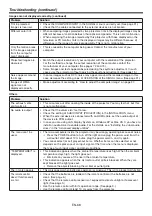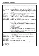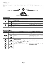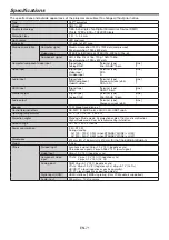
EN-74
375
83
91
136
310
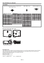
Dimension drawings (unit: mm)
Connectors
COMPUTER/COMPONENT VIDEO IN, MONITOR OUT
(Mini D-SUB 15-pin)
11
6
1 5
10
15
HDMI (HDMI 19-pin)
19 1
2
18
SERIAL (D-SUB 9-pin)
1 5
6
9
COMPUTER/COMPONENT
VIDEO IN
Pin No.
Spec.
1
R (RED)/C
R
2
G (GREEN)/Y
3
B (BLUE)/C
B
4
GND
5
GND
6
GND
7
GND
8
GND
9
DDC 5V
10
GND
11
GND
12
DDC Data
13
HD/CS
14
VD
15
DDC Clock
MONITOR OUT
Pin No.
Spec.
1
R (RED)/C
R
2
G (GREEN)/Y
3
B (BLUE)/C
B
4
-
5
GND
6
GND
7
GND
8
GND
9
-
10
GND
11
-
12
-
13
HD/CS
14
VD
15
-
Pin No.
Spec.
1
TMDS Data 2 +
2
TMDS Data 2 Shield
3
TMDS Data 2 -
4
TMDS Data 1 +
5
TMDS Data1 Shield
6
TMDS Data 1 -
7
TMDS Data 0 +
8
TMDS Data 0 Shield
9
TMDS Data 0 -
10
TMDS Clock +
11
TMDS Clock Shield
12
TMDS Clock -
13
CEC
14
-
15
SCL
16
SDA
17
DDC Ground
18
+5 V Power
19
Hot Plug Detect
Pin No.
Name
I/O
1
–
–
2
TXD
IN
3
RXD
OUT
4
–
–
5
GND
–
6
–
–
7
–
–
8
–
–
9
–
–
Specifi cations (continued)
Kensington Lock
This projector has a Kensington Security Standard connector for use with Kensington MicroSaver Security System.
Refer to the information that came with the Kensington System for instructions on how to use it to secure the
projector. Please contact Kensington Technology Group below.
Kensington Technology Group
2855 Campus Drive
San Mateo, CA 94403, U.S.A.
Phone: +1- (650)572-2700
Fax: +1- (650)572-9675

