- 35 -
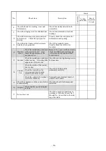
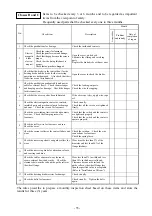
Classes B and C
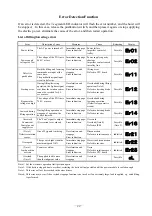
No.
Check item
Description
Month
Acceptability
Problem
and remedy
Date of
completion
of repair
1
Check the pushbuttons for damage.
Check the inside and contacts.
2
Electro-
magnetic
brake
electro-
magnet
Check the screws for looseness.
Check the parts for wear and damage.
Check that the gap between the cores is
proper.
Check that the lining thickness is
proper.
Check that no pins have dropped.
Open the cover, and check.
Lubricate the sliding and revolving
parts.
Replace the brake disks with new ones.
3
Check that the diode (in the control box) for the
hoisting brake and the diode for the traversing
operation are not damaged. Also check that their
lead wires are not disconnected.
Open the cover to check the diodes.
4
Check the pushbutton pendant cable and power
cable for external flaws. Check the messenger
and hanging wire for damage. Check the hanger
for disconnection.
Check the leading-out ports.
Check the wire for sagging.
5
Check that the wire rope has been lubricated.
If the wire rope is dry, apply wire rope
oil.
6
Check the electromagnetic contactor, contacts,
insulated parts and mechanical parts for damage
and wear. Check the screws for looseness.
Check visually.
Check that all the screws are tightened
firmly.
7
Check the overwinding limit switch and contacts
for wear. Check the clamping screws for
looseness.
Check that the switch and the contacts
are tightened properly.
Check that the switch and the contacts
operate properly.
8
Check the trolley wire for looseness and rust.
Check the wires.
9
Check the current collector for contact failure and
wear.
Check the rotation. Check the wire
connections for looseness.
Check the spring force.
10
Check the traversing wheels and guide rollers for
wear.
Wear must be less than 5% of the
diameter and less than 50% of the
flange thickness.
11
Check the traversing brake for attraction, release
and coasting condition.
12
Check the rail for abnormal wear, loosened
seams, external flaws and cracks. Check the
clearance between the rail and the guide roller or
the wheel flange.
Wear less than 5% in width and less
than 10% in thickness is allowed.
Clearance between the rail and the
guide roller or the wheel flange less
than the specified value is acceptable.
(Refer to “Installation on I-Beam”.)
13
Check the hoisting brake resistor for damage.
Check visually.
14
Check the bolts for looseness.
Check visually. Tighten the bolts
again.
The rules prescribe to prepare a monthly inspection sheet based on these items and store the
results for three (3) years.
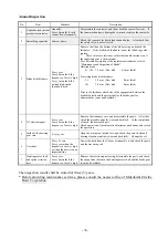
Items to be checked every 3 or 6 months and to be regarded as important
items from the viewpoint of safety.
Frequently used parts shall be checked every one to three months.
Summary of Contents for UM 10t
Page 51: ... 47 Structural Drawing of Hoist Main Body 5t 10t PA00531 ...
Page 52: ... 48 Structural Drawing of Electric Traversing Unit Monorail Type 10t P288922 ...
Page 53: ... 49 Structural Drawing of Electric Traversing Unit Double rail type 5t PA00483 ...
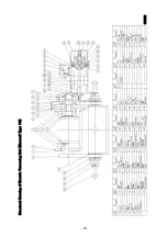
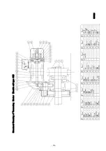
Page 54: ... 50 Structural Drawing of Traversing Mortor Double rail type 10t P276926 ...
Page 55: ... 51 Structural Drawing of Hook Block 5t PG49975 ...
Page 56: ... 52 Structural Drawing of Hook Block 10t PG49976 ...


