-
25
-
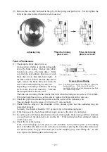
(9) Remove the assembly bolt used in Step (6), fit the spring, and put the lid. Evenly tighten the
bolts in the same matter when they were loosened.
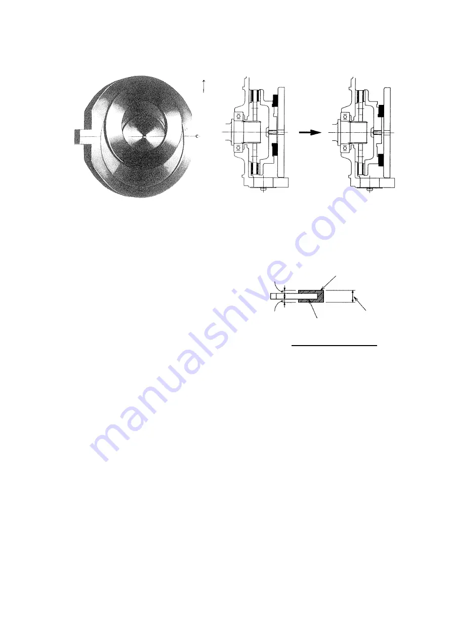
Up
Adjusting ring
When the braking
When the braking
plate is new.
plate is worn out.
Points of Maintenance
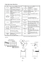
(1) Checking the brake disks for wear
An inspection window is provided diagonally
above the brake casing. Remove the rubber
lid, and you can see the brake disks. Make
sure that the approximate thickness of each
brake disk is more than that shown right. If
the brake disk is thinner than the disk shown
right, remove the brake disk, and check the
size of the remaining lining on each side.
Depending on working conditions, the lining
on the sides has worn unevenly. Measure
the lining thickness on both sides.
The brake disk working life has reached the limit when the lining on one side is 0.5 mm thick.
When the lining has worn to such an extent, replace the brake disk with a new one.
(2) Check the gap between adsorbing surface and the center of the stationary core.
The gap should be in the range of 0.1 mm to 0.3 mm, normally.
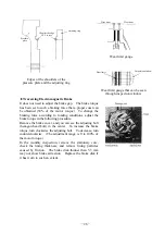
(3) Check that the edges of the shoulders of the pressure plate and the adjusting ring are
chamfered properly.
Normally, the chamfer should be C0.2 or less (refer to the following figure).
(4) If the brake gear has been disassembled, apply grease to the inner circumference
(5) Do not forget to fit the packing between the electromagnetic brake casing and the stationary
core and between the stationary core and the lid. If the packing has been damaged, replace
it with a new one.
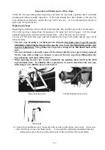
(6) Check the wear limit gauge.
If the wear limit gauge (at the groove or the shoulder) of the pressure plate or the braking
plate is invisible (the plate is worn out to the wear limit), replacing the brake disk with a new
one cannot reduce the gap and cannot prevent the adjusting ring from falling off. In this
case, replace the braking plate with a new one.
Core
Lining
0.5 mm or more
0.5 mm or more
5t,10t type
:
7.8 mm o r more
Cross section of lining
Note: The lining wear limit shown above is a limit for
mechanical use. If the inverter is used for
operation, observe the limit dimension specified
for “annual inspection”.
Summary of Contents for UM 10t
Page 51: ... 47 Structural Drawing of Hoist Main Body 5t 10t PA00531 ...
Page 52: ... 48 Structural Drawing of Electric Traversing Unit Monorail Type 10t P288922 ...
Page 53: ... 49 Structural Drawing of Electric Traversing Unit Double rail type 5t PA00483 ...
Page 54: ... 50 Structural Drawing of Traversing Mortor Double rail type 10t P276926 ...
Page 55: ... 51 Structural Drawing of Hook Block 5t PG49975 ...
Page 56: ... 52 Structural Drawing of Hook Block 10t PG49976 ...

