-
7
-
○
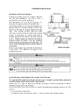
For suspended hoists
Remove paint coating and rust from the point of installation. Install it on a steel structure that
complies with Class C or Class D electrical grounding requirements.
(Make sure that the main body will not be electrically insulated.)
When the hoist is installed on a wooden structure, ground the hoist main body with electrical
wire of 2.6 mm in diameter or greater.
Warning
●
Be sure to ground the crane. In addition to the grounding, provide the electrical circuit with a ground fault circuit breaker.
●
Ground the crane to type C or type D grounding specification.
●
Comply with Electrical Standard for Industrial Machinery and Naisen Kitei (Japanese Standard for Electrical
Wiring) for the grounding and installation of the ground fault circuit breaker.
⋅
This is to prevent electric shock if a ground fault occurs.
・
Electrical Wiring
Observe the technical standards for electric equipment and the regulations for internal wiring.
The hoist can be supplied with power through trolley wire or power supply cable.
1. Trolley type
To prevent accidents, such as an electrical shock, use an insulated trolley. Various insulated
trolleys are commercially available. Select a trolley wire conductor with proper capacity and
specifications.
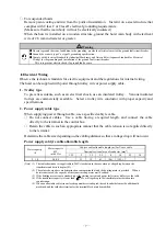
2. Power supply cable type
When supplying power through cable, use a specified cabtyre cable.
○
Do not connect cables. Use a cable having a required length, and connect the cable
directly to the terminal in the control box.
○
Retain the cable in such an appropriate manner that the cable tension is not applied directly
to the terminal.
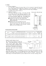
Determine the cable size depending on the cabling distance so that a voltage drop will not occur.
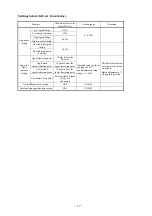
Power supply cabtyre cable allowable length
Hoist capacity
(t)
Motor capacity
kW
(at 60 Hz)
Cabtyre cable allowable length (m) for 3-core cable
Nominal sectional area of conductor (mm
2
)
1.25 2 3.5 5.5 8 14 22 30
5
、
10 5.0/6.0
-
21
39
61
(86)
(152)
(Note) (1) The table shown above is applicable to 200V class hoists in the case when a voltage drop between the
transformer and hoist is kept at 10%.
(2) The values shown above are determined on consumption that only the hoisting motor is provided. When a
hoist crane is used, the capacity of the crane traveling motor must be added.
(3) If the hoisting motor is not a standard type (the starting current and power factory may differ), see the table.
(4) If the transformer capacity is lower than
3
EIs
, a voltage drop in the transformer must be taken into
consideration.
(5) When an allowable cable size enclosed in parentheses is adopted, the cable outlet hole must be additionally
machined, and the solderless terminal or the terminal block must be modified.
!
Summary of Contents for UM 10t
Page 51: ... 47 Structural Drawing of Hoist Main Body 5t 10t PA00531 ...
Page 52: ... 48 Structural Drawing of Electric Traversing Unit Monorail Type 10t P288922 ...
Page 53: ... 49 Structural Drawing of Electric Traversing Unit Double rail type 5t PA00483 ...
Page 54: ... 50 Structural Drawing of Traversing Mortor Double rail type 10t P276926 ...
Page 55: ... 51 Structural Drawing of Hook Block 5t PG49975 ...
Page 56: ... 52 Structural Drawing of Hook Block 10t PG49976 ...

