


Chapter 5 Adjustment
5-9
(2) Adjusting the cutting rate
To adjust the cutting rate, the CNC axis specification parameter clamp speed (clamp) and
acceleration/deceleration time constant (G1t
) are adjusted. The in-position width at this time
must be set to the same value as actual cutting.
• Determining the clamp rate and adjusting the acceleration/deceleration time constant
(Features)
The maximum cutting rate (clamp speed) can be determined freely.
(Adjustment)
Carry out cutting feed reciprocation operation with no dwell at the maximum
cutting rate and adjust the acceleration/deceleration time constant so that the
maximum current command value during acceleration/deceleration is within the
range shown below.
• Setting the step acceleration/deceleration and adjusting the clamp speed
(Features)
The acceleration/deceleration time constant is determined with the position loop
in the servo, so the acceleration/deceleration F
⊿
T can be reduced.
(Adjustment)
Set 1 (step) for the acceleration/deceleration time constant and carry out cutting
feed reciprocation operation with no dwell. Adjust the cutting feed rate so that
the maximum current command value during acceleration/deceleration is within
the range shown below, and then set the value in the clamp speed.
<Maximum current command value>
For the maximum current command value during acceleration/deceleration, the maximum current
command value for one second is output to MAX current 1 and MAX current 2 on the CNC servo
monitor screen and observed.
Change "mon" in the servo function selection 3 (SV034: SSF3) and display.
No. Abbrev.
Parameter
name
Explanation
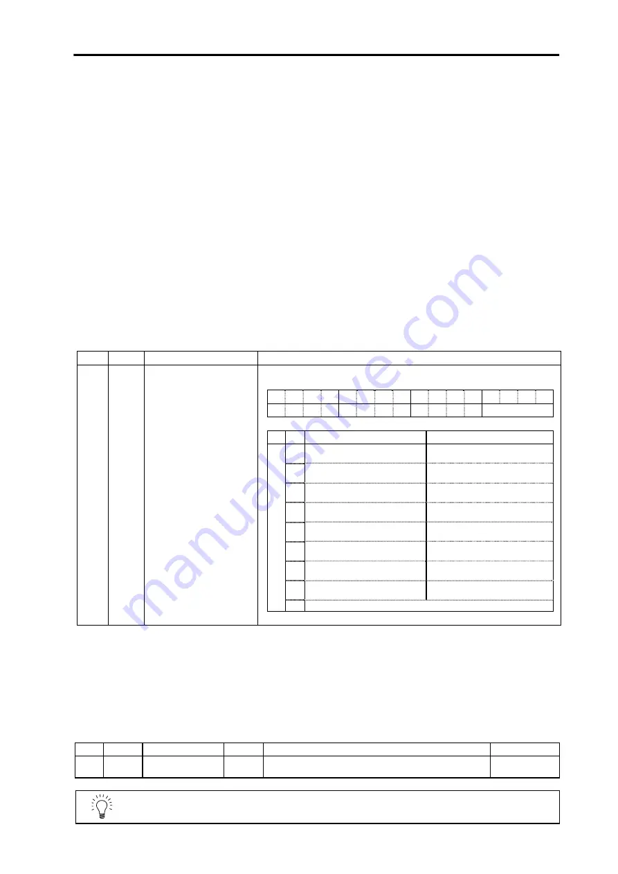
SV034
SSF3 Servo function selection 3
The display data for the maximum current value on the servo monitor is
determined with the following parameter.
F
E
D
C
B
A
9
8
7
6 5 4 3 2
1
0
daf2 daf1 dac2 dac1
mon
bit
mon
MAX current 1
MAX current 2
0
Max. current command value
(%) when power is turned ON
Max. current command value (%)
for 1 second
1
Max. current command value
(%) for 1 second
Max. current FB value (%) for 1
second
2
Max. current FB value (%) when
power is turned ON
Max. current FB value (%) for 1
second
3
Load inertia rate (SV059 setting
value)
−
4
Adaptive filter operation
frequency (Hz)
Adaptive filter operation gain (%)
5
PN bus voltage (V)
Regenerative operation
frequency monitor (times/sec)
6
Maximum estimated torque for
one second (%)
Maximum current FB value for
one second (%)
7
Maximum estimated torque for
one second (%)
Maximum disturbance torque for
two seconds (%)
0~3
8~F Setting prohibited
(3) Adjusting the in-position width
Because there is a response delay in the servomotor drive due to position loop control, a "settling
time" is also required for the motor to actually stop after the command speed from the CNC
reaches 0.
The movement command in the next block is generally started after it is confirmed that the
machine has entered the "in-position width" range set for the machine.
The in-position width is effective even when the standard servo parameters are set. However, it
may follow the CNC parameters, so refer to the CNC Instruction Manual for the setting.
No.
Abbrev.
Parameter name
Unit
Explanation
Setting range
SV024 INP In-position
detection
width
μ
m
Set 50 as a standard.
Set the precision required for the machine.
0 ~ 32767
POINT
The in-position width setting and confirmation availability depend on the CNC
parameters
Summary of Contents for MELDAS MDS-B-SVJ2 Series
Page 1: ......
Page 2: ......
Page 4: ......
Page 6: ......
Page 46: ......
Page 92: ......
Page 108: ......
Page 152: ......
Page 186: ......
Page 194: ......
Page 218: ......
Page 260: ......
Page 282: ......
Page 283: ...12 1 Chapter 12 Inspections 12 1 Inspections 12 2 12 2 Life parts 12 2 ...
Page 294: ......
Page 297: ......


