


A - 24
MANUAL PAGE ORGANIZATION
The symbols used in this manual are shown below.
A serial No. is inserted in the "*" mark.
Symbol Description
[Pr. * ]
Symbol that indicates positioning parameter and OPR parameter item.
[Da. * ]
Symbol that indicates positioning data, block start data and condition data item.
[Md. * ]
Symbol that indicates monitor data item.
[Cd. * ]
Symbol that indicates control data item.
QD77MS
Symbol that indicates correspondence to only QD77MS.
LD77MS
Symbol that indicates correspondence to only LD77MS.
QD77GF
Symbol that indicates correspondence to only QD77GF.
[RJ010 mode]
Symbol that indicates specifications during the communication mode compatible with
MR-J4-B-RJ010.
This mode corresponds to the MR-J4-_B_-RJ010+MR-J3-T10 servo amplifier.
When using the virtual servo amplifier function, it operates in MR-J4-B-RJ010
communication mode regardless of the communication mode setting.
[CiA402 mode]
Symbol that indicates specifications during the communication mode compatible with
CiA402.
This mode corresponds to the MR-J4-_GF_(-RJ) servo amplifier and others.
Representation of numerical values used in this manual.
Buffer memory addresses, error codes and warning codes are represented in
decimal.
X/Y devices are represented in hexadecimal.
Setting data and monitor data are represented in decimal or hexadecimal. Data
ended by "H" or "h" is represented in hexadecimal.
(Example) 10.........Decimal
10H......Hexadecimal
Representation of buffer memory address used in this manual.
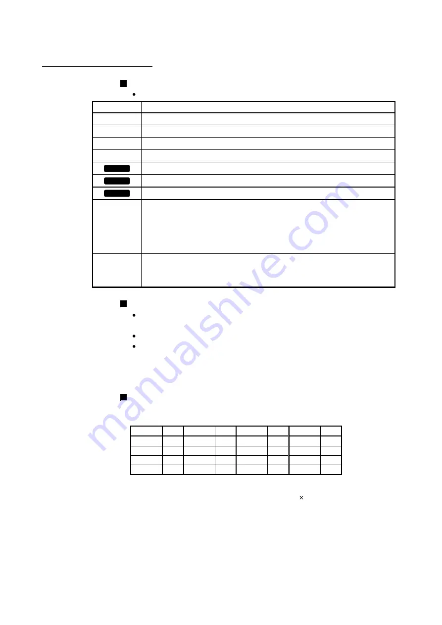
In the buffer memory address, "n" in "32800+10n", etc. indicates a value
corresponding to axis No. such as the following table.
Axis
No. n Axis
No.
n Axis
No.
n Axis
No. n
1 0 5 4 9 8 13 12
2 1 6 5 10 9 14 13
3 2 7 6 11 10 15 14
4 3 8 7 12 11 16 15
(Note-1): Calculate as follows for the buffer memory address corresponding to each axis.
(Example) For axis No. 16
32800+10n ([Pr.300] Servo input axis type)=32800+10 15=32950
(Note-2): The range from axis No.1 to 2 (n=0 to 1) is valid in the 2-axis module, the range from axis No.1 to 4 (n=0 to 3)
is valid in the 4-axis module, and the range from axis No.1 to 8 (n=0 to 7) is valid in the 8-axis module.
Summary of Contents for LD77MH
Page 2: ......
Page 48: ...1 16 Chapter1 Outline of Synchronous Control MEMO ...
Page 84: ...2 36 Chapter 2 Input Axis Module MEMO ...
Page 104: ...3 20 Chapter 3 Cam Function MEMO ...
Page 168: ...4 64 Chapter 4 Synchronous Control MEMO ...
Page 234: ...Appendix 18 Appendices MEMO ...
Page 237: ......


