


6 - 8
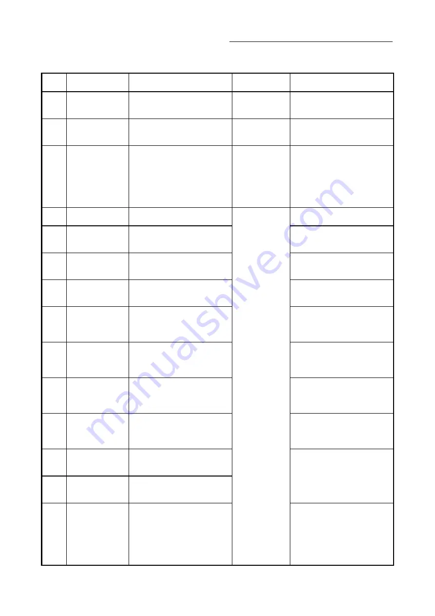
Chapter 6 Troubleshooting (Synchronous Control)
Error
No.
Error name
Error
Operation status at
error occurrence
Corrective action
741
(2E5h)
Outside speed change
ratio denominator
range
The synchronous parameter "[Pr.437]
Speed change ratio: Denominator" is
set to 0 or lower"
Synchronous control
does not start.
Set a value within the range of 1 to
2147483647.
742
(2E6h)
Outside speed change
gear smoothing time
constant range
The synchronous parameter "[Pr.435]
Speed change gear smoothing time
constant" is set other than 0 to 5000.
Synchronous control
does not start.
Set a value within the range of 0 to
5000.
743
(2E7h)
Speed change gear
overflow
Overflow (sign reversion) occurred in
input values, because the speed
change ratio of speed change gear is
too large.
Synchronous control
is immediately
stopped.
• Set a smaller absolute value for the
synchronous parameter "[Pr.436]
Speed change ratio: Numerator".
• Set a larger value for the synchronous
parameter "[Pr.437] Speed change
ratio: Denominator".
• Decrease the input axis speed.
750
(2EEh)
Outside cam No. range
The synchronous parameter "[Pr.440]
Cam No." is set to other than 0 to 256.
Synchronous control
does not start.
Set a value within the range of 0 to 256.
751
(2EFh)
Cam not registered
Cam data specified in the synchronous
parameter "[Pr.440] Cam No." does not
exist on the cam open area.
Specify the cam No. of an existing cam
data.
752
(2F0h)
Outside cam axis
length per cycle range
The synchronous parameter "[Pr.439]
Cam axis length per cycle" is set to 0 or
lower.
Set a value within the range of 1 to
2147483647.
753
(2F1h)
Outside output axis
smoothing time
constant range
The synchronous parameter "[Pr.447]
Output axis smoothing time constant" is
set to other than 0 to 5000.
Set a value within the range of 0 to
5000.
760
(2F8h)
Outside setting method
of current value per
cycle after main shaft
gear range
The synchronous parameter "[Pr.460]
Setting method of current value per
cycle after main shaft gear" is set to
other than 0 to 2.
Set a value within the range of 0 to 2.
761
(2F9h)
Outside current value
per cycle after main
shaft gear (Initial
setting) range
The synchronous parameter "[Pr.465]
Current value per cycle after main shaft
gear (Initial setting)" is other than 0 to
(Cam axis length per cycle -1).
Set within the range of 0 to (Cam axis
length per cycle -1).
762
(2FAh)
Outside setting method
of current value per
cycle after auxiliary
shaft gear range
The synchronous parameter "[Pr.461]
Setting method of current value per
cycle after auxiliary shaft gear" is set to
other than 0 to 2.
Set a value within the range of 0 to 2.
763
(2FBh)
Outside current value
per cycle after auxiliary
shaft gear (Initial
setting) range
The synchronous parameter "[Pr.466]
Current value per cycle after auxiliary
shaft gear (Initial setting)" is other than 0
to (Cam axis length per cycle - 1).
Set within the range of 0 to (Cam axis
length per cycle - 1).
764
(2FCh)
Outside cam axis
position restoration
object range
The synchronous parameter "[Pr.462]
Cam axis position restoration object" is
set to other than 0 to 2.
Set a value within the range of 0 to 2.
765
(2FDh)
Outside setting method
of
cam reference
position range
The synchronous parameter "[Pr.463]
Setting method of cam reference
position " is set to other than 0 to 2.
766
(2FEh)
Outside setting method
of cam axis current
value per cycle range
• The synchronous parameter "[Pr.464]
Setting method of cam axis current
value per cycle" is set to other than 0
to 3.
• "3: Current value per cycle after
auxiliary shaft gear" is established
when the auxiliary shaft does not exist.
• Set a value within the range of 0 to 3.
• Set other than "3: Current value per
cycle after auxiliary shaft gear" when
the auxiliary shaft does not exist.
Summary of Contents for LD77MH
Page 2: ......
Page 48: ...1 16 Chapter1 Outline of Synchronous Control MEMO ...
Page 84: ...2 36 Chapter 2 Input Axis Module MEMO ...
Page 104: ...3 20 Chapter 3 Cam Function MEMO ...
Page 168: ...4 64 Chapter 4 Synchronous Control MEMO ...
Page 234: ...Appendix 18 Appendices MEMO ...
Page 237: ......


