


4 - 5
Chapter 4 Synchronous Control
4.1.3 Main shaft clutch parameters
Setting item
Setting details
Setting value
Default
value
Buffer memory
address
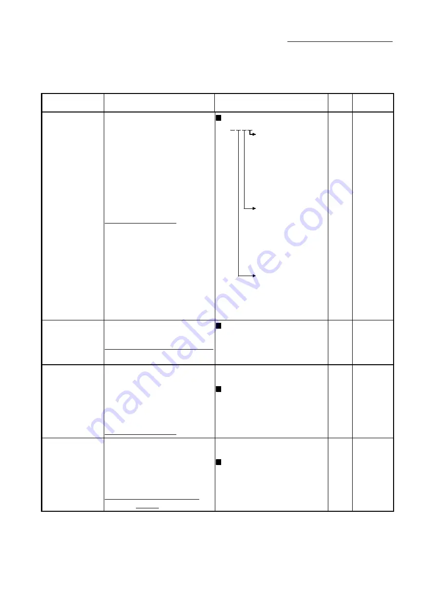
[Pr.405]
Main shaft clutch
control setting
• Set the control method for the clutch.
Fetch cycle: Operation cycle
Set in hexadecimal.
H
ON control mode
0: No clutch
1: Clutch command
ON/OFF
2: Clutch command
leading edge
3: Clutch command
trailing edge
4: Address mode
5: High speed input
request
OFF control mode
0: OFF control invalid
1: One-shot OFF
2: Clutch command
leading edge
3: Clutch command
trailing edge
4: Address mode
5: High speed input
request
High speed input request
signal
0 to F: High speed
input request
signal from axis 1
to axis 16
(Note-1)
0000h 36408+200n
[Pr.406]
Main shaft clutch
reference address
setting
• Set the reference address for the clutch.
Fetch cycle: At start of synchronous control
Set in decimal.
0: Current value after composite main
shaft gear
1: Current value per cycle after main
shaft gear
0 36409+200n
[Pr.407]
Main shaft clutch ON
address
• Set the clutch ON address for address
mode. (This setting is invalid except
during address mode.)
• If the address is out of the range from 0 to
(Cam axis length per cycle - 1), the
address is converted to a value within
range.
Fetch cycle: Operation cycle
Set in decimal.
-2147483648 to 2147483647
[Main input axis position units
(Note-2)
, or
cam axis cycle units
(Note-3)
]
0
36410+200n
36411+200n
[Pr.408]
Travel value before
main shaft clutch ON
• Set the travel value for the distance
between the clutch ON condition
completing and the clutch closing.
• Set a positive value when the reference
address is increasing, and a negative
value when it is decreasing.
Fetch cycle: At completing clutch ON
condition
Set in decimal.
-2147483648 to 2147483647
[Main input axis position units
(Note-2)
, or
cam axis cycle units
(Note-3)
]
0
36412+200n
36413+200n
n: Axis No.-1
(Note-1): The range from axis 1 to 2 is valid in the 2-axis module, from axis 1 to 4 is valid in the 4-axis module, from axis 1 to 8 is valid in the
8-axis module, and from axis 1 to 16 is valid in the 16-axis module.
(Note-2): Main input axis position units (Refer to Chapter 2)
(Note-3): Cam axis cycle units (Refer to Section 4.5.1)
Summary of Contents for LD77MH
Page 2: ......
Page 48: ...1 16 Chapter1 Outline of Synchronous Control MEMO ...
Page 84: ...2 36 Chapter 2 Input Axis Module MEMO ...
Page 104: ...3 20 Chapter 3 Cam Function MEMO ...
Page 168: ...4 64 Chapter 4 Synchronous Control MEMO ...
Page 234: ...Appendix 18 Appendices MEMO ...
Page 237: ......


