


4 - 23
Chapter 4 Synchronous Control
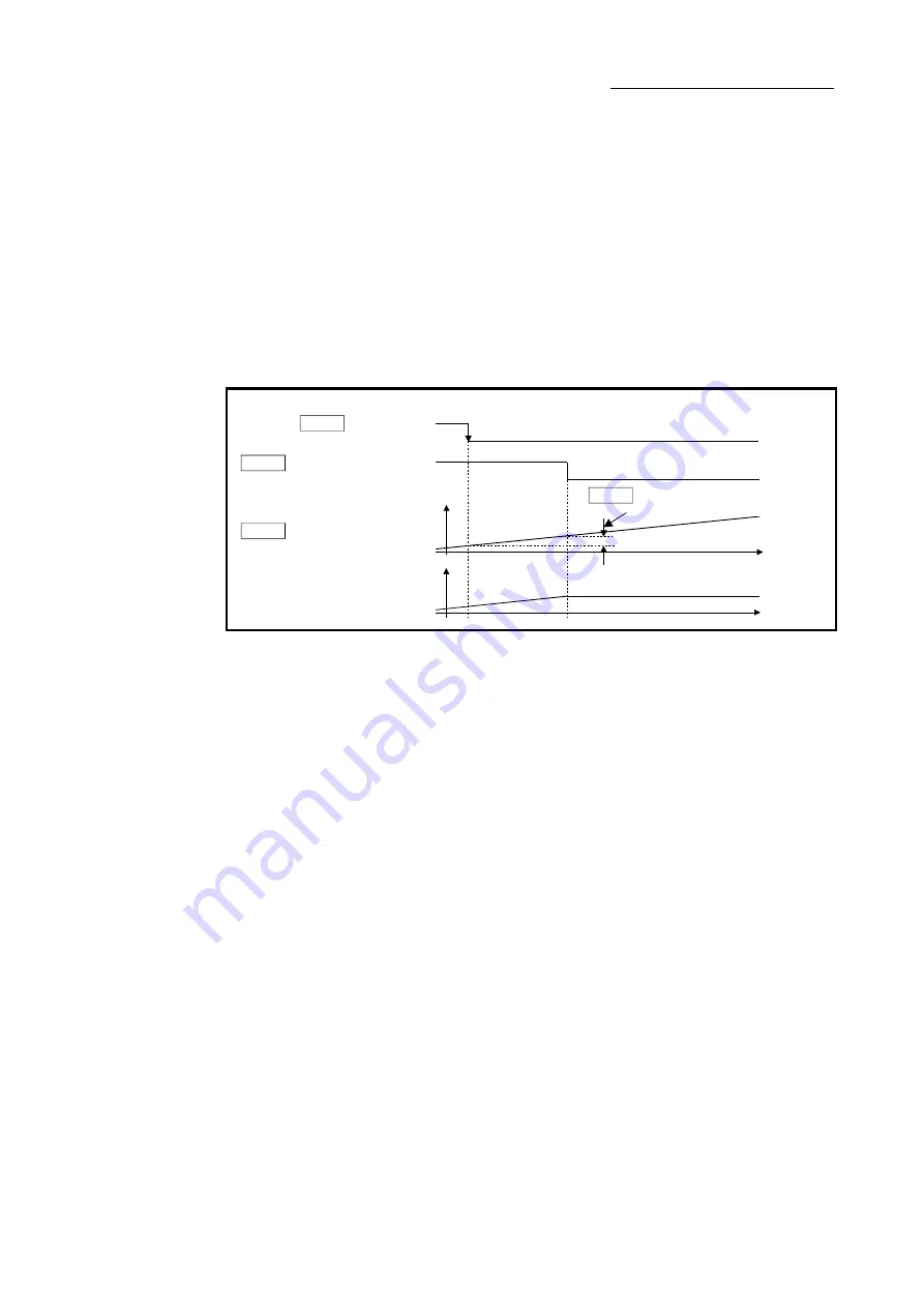
[Pr.427] Travel value before auxiliary shaft clutch OFF
Set the travel value of the reference address with a signed value between the clutch OFF
condition completing and the clutch opening.
1 to 2147483647 (Positive value) ........ Used when the reference address is increasing in
direction.
0 ............................................................. No movement amount (The clutch is immediately
turned OFF with the clutch OFF condition
completing.)
-2147483648 to -1(Negative value) ..... Used when the reference address is decreasing in
direction.
Travel value after clutch
Clutch OFF condition is completed
(Example:
clutch command OFF)
Cd.403 Auxiliary shaft
Md.423 Auxiliary shaft clutch
ON/OFF status
Auxiliary shaft current value or
Md.402 Current value per cycle
after auxiliary shaft gear
Pr.427 Travel value before auxiliary shaft
clutch OFF (Positive value)
[Pr.428] Auxiliary shaft clutch smoothing method
Set the smoothing method for clutch ON/OFF.
Refer to Section 4.3.3 for details.
0: Direct ..................................................... No smoothing.
1: Time constant method (Exponent) ...... Smoothing with an exponential curve based on
the time constant setting.
2: Time constant method (Linear) ............ Smoothing with linear acceleration/deceleration
based on the time constant setting.
3: Slippage method (Exponent) ............... Smoothing with an exponential curve based on
the slippage amount setting.
4: Slippage method (Linear) ..................... Smoothing with linear acceleration/deceleration
based on the slippage amount setting.
[Pr.429] Auxiliary shaft clutch smoothing time constant
Set a time constant when the time constant method is set in "[Pr.428] Auxiliary shaft clutch
smoothing method".
The time constant setting applies for clutch ON/OFF.
Summary of Contents for LD77MH
Page 2: ......
Page 48: ...1 16 Chapter1 Outline of Synchronous Control MEMO ...
Page 84: ...2 36 Chapter 2 Input Axis Module MEMO ...
Page 104: ...3 20 Chapter 3 Cam Function MEMO ...
Page 168: ...4 64 Chapter 4 Synchronous Control MEMO ...
Page 234: ...Appendix 18 Appendices MEMO ...
Page 237: ......


