


5 - 7
Chapter 5 Synchronous Control Initial Position
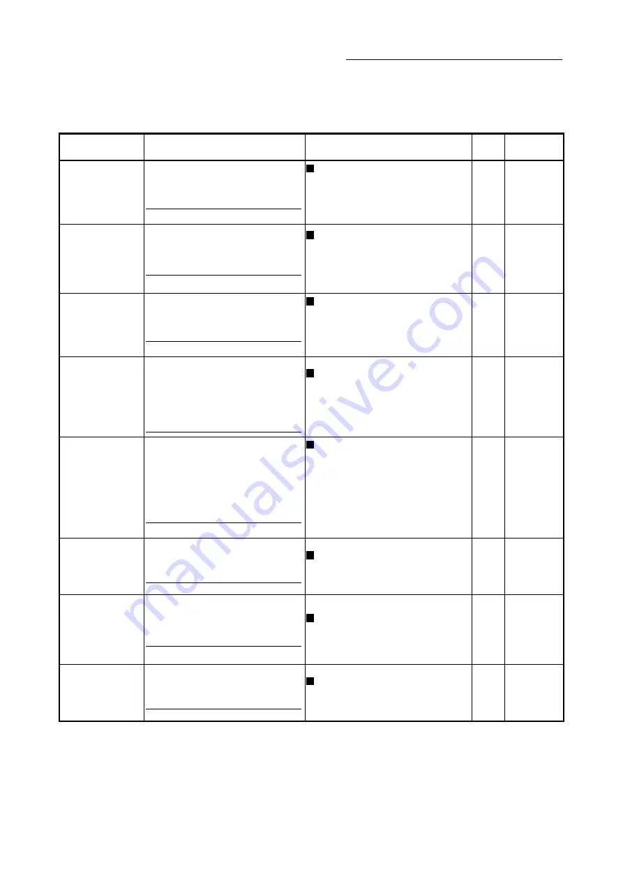
5.2 Synchronous control initial position parameters
Setting item
Setting details
Setting value
Default
value
Buffer memory
address
[Pr.460]
Setting method of
current value per cycle
after main shaft gear
• Select the setting method for the current
value per cycle after main shaft gear.
Fetch cycle: At start of synchronous control
Set in decimal.
0: Previous value
1: Initial setting value of current value per
cycle after main shaft gear ([Pr.465])
2: Calculate from input axis
0 36500+200n
[Pr.461]
Setting method of
current value per cycle
after auxiliary shaft
gear
• Select the setting method for the current
value per cycle after auxiliary shaft gear.
Fetch cycle: At start of synchronous control
Set in decimal.
0: Previous value
1: Initial setting value of current value per
cycle after auxiliary shaft gear ([Pr.466])
2: Calculate from input axis
0 36501+200n
[Pr.462]
Cam axis position
restoration object
• Select the object to restore the cam axis
position.
Fetch cycle: At start of synchronous control
Set in decimal.
0: Cam axis current value per cycle
restoration
1: Cam reference position restoration
2: Cam axis feed current value restoration
0 36502+200n
[Pr.463]
Setting method of cam
reference position
• Select the setting method for the cam
reference position.
• Set for the cam axis current value per
cycle restoration or the cam axis feed
current value restoration.
Fetch cycle: At start of synchronous control
Set in decimal.
0: Previous value
1: Initial setting value of cam reference
position
2: Feed current value
2 36503+200n
[Pr.464]
Setting method of cam
axis current value per
cycle
• Select the setting method for the cam axis
current value per cycle.
• Set for the cam reference position
restoration or the cam axis feed current
value restoration.
Fetch cycle: At start of synchronous control
Set in decimal.
0: Previous value
1: Initial setting value of cam axis current
value per cycle
2: Current value per cycle after main shaft
gear
3: Current value per cycle after auxiliary
shaft gear
0 36504+200n
[Pr.465]
Current value per
cycle after main shaft
gear (Initial setting)
• Set the initial value of the current value
per cycle after main shaft gear.
Fetch cycle: At start of synchronous control
Set in decimal.
0 to (Cam axis length per cycle - 1)
[Cam axis cycle units
(Note-1)
]
0
36506+200n
36507+200n
[Pr.466]
Current value per
cycle after auxiliary
shaft gear
(Initial setting)
• Set the initial value of the current value
per cycle after
auxiliary shaft gear.
Fetch cycle: At start of synchronous control
Set in decimal.
0 to (Cam axis length per cycle - 1)
[Cam axis cycle units
(Note-1)
]
0
36508+200n
36509+200n
[Pr.467]
Cam reference
position
(Initial setting)
• Set the initial value of the cam reference
position.
Fetch cycle: At start of synchronous control
Set in decimal.
-2147483648 to 2147483647
[Output axis position units
(Note-2)
]
0
36510+200n
36511+200n
n: Axis No.-1
(Note-1): Cam axis cycle units (Refer to Section 4.5.1)
(Note-2): Output axis position units (Refer to Section 4.5.1)
Summary of Contents for LD77MH
Page 2: ......
Page 48: ...1 16 Chapter1 Outline of Synchronous Control MEMO ...
Page 84: ...2 36 Chapter 2 Input Axis Module MEMO ...
Page 104: ...3 20 Chapter 3 Cam Function MEMO ...
Page 168: ...4 64 Chapter 4 Synchronous Control MEMO ...
Page 234: ...Appendix 18 Appendices MEMO ...
Page 237: ......


