


4. PARAMETERS FOR POSITIONING CONTROL
4
−
4
1) Travel value per feedback pulse
S=10[mm]
Z
1
Z
2
=10[mm]
25
1
I=
=
25 8192
10[mm]
Pf
S
=0.000049[mm]....
I=0.0001[mm]
∆
∆ ∆
∆
2) Unit magnification (A
M
)
Since
∆
l is 0.0001[mm], the unit magnification (A
M
) is "1".
3) Travel distance per revolution (A
L
)
A
L
=
25
=0.4[mm]=400.0[ m]
10[mm] 1
4) Number of pulses per revolution (A
P
)
A
P
= 8192 [PLS/rev] ... fixed according to the encoder model.
(2) Setting method 2
If A
L
cannot be set by using setting method 1, calculate the numerator and
denominator of the electronic gear, and set A
P
as the numerator and A
L
×
A
M
as the denominator.
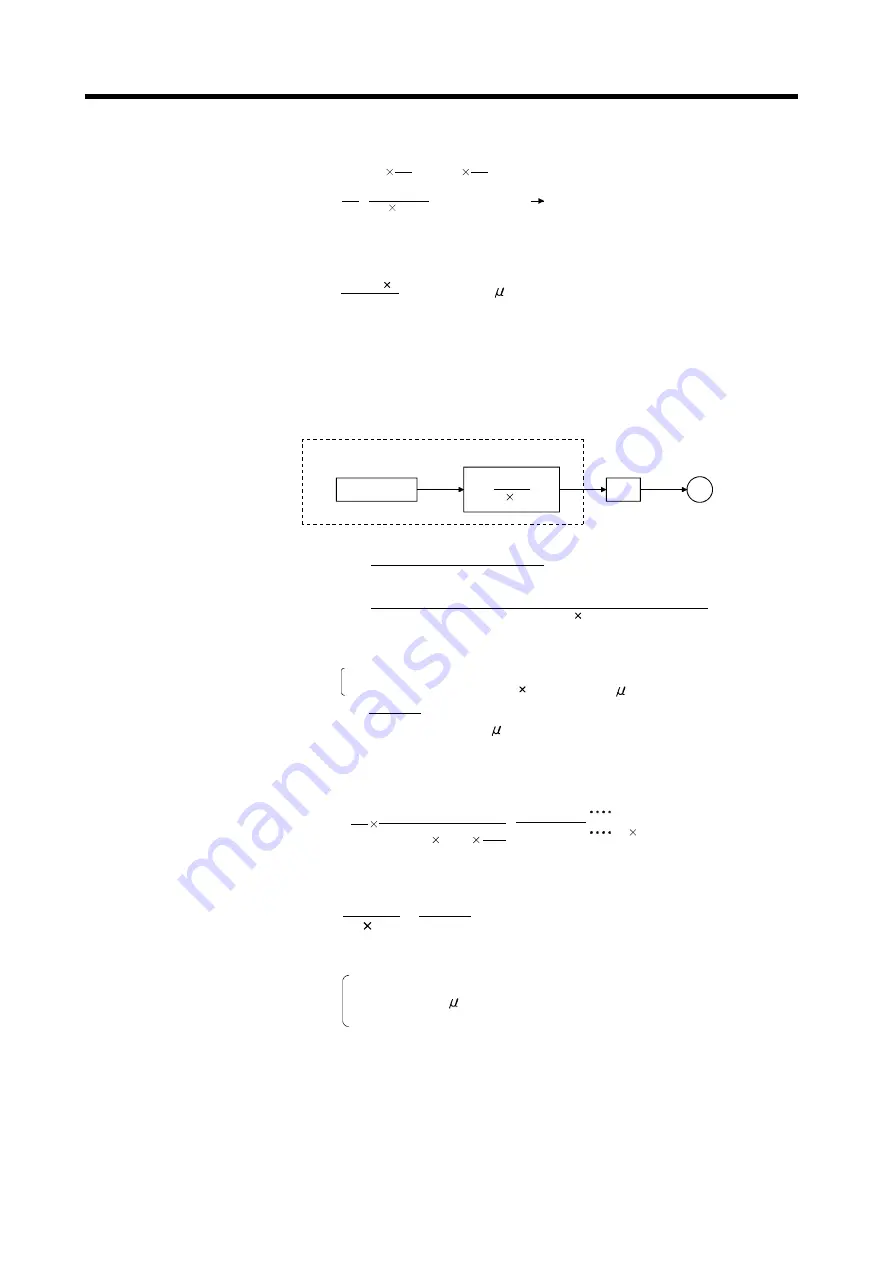
Command
A
P
A
L
A
M
Servo system CPU
Electronic gear
Amplifier
M
Motor
The electronic gear is represented by the following relational expression.
Electronic gear =
Number of feedback pulses (Pf)
Travel value per revolution ( S)
=
Number of pulses per revolution (A
P
)
Travel value per motor revolution (A
L
) unit magnification (A
M
)
∆
Example: With the example configuration shown above, and under the following
conditions(e);
Gear ratio=Z
1
: Z
2
=1 : 39
Ball screw pitch=25.4[mm]=25.4 1000 = 25400.0[ m]
A
L
=
29
25.4[mm]
=0.65128205[mm]
=651.28205[ m]
and A
L
cannot be set, calculate as follows....
Electronic gear
Elecronic gear
Pf
S
25.4[mm] 1000
39
1
8192[PLS]
=
25400.0[
µ
m]
319488
=
A
P
A
L
A
M
∆
Here, since the setting range of A
P
is 1 to 65535 [PLS] and that of A
L
is 0.1 to 6553.5 [
µ
m], reduce them to within their setting ranges.
A
P
A
L
A
M
=
19968
1587.5
Thus,
A
P
=19968[PLS]
A
L
(Note)=1587.5[ m] .... and set the following values
A
M
=1


