


18. Interface specifications
MiR250 Shelf Carrier User Guide (en) 03/2021 - v.1.4 ©Copyright 2021: Mobile Industrial Robots A/S.
238
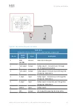
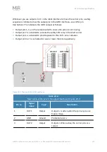
Pin no.
Signal
name
Type
Description
LAMP_24_
V
Emergency stop box.
8
NC
Not connected to the robot.
9
NC
Not connected to the robot.
10
NC
Not connected to the robot.
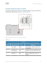
18.2 Right side interfaces
This section describes the general purpose interfaces that are used to interface to the top
module on the right side of the robot.
GPIO A and B
The GPIO interfaces have the following pins:
•
Four inputs, for use with 24 V, but robust against 48 V.
•
Four outputs, for use with 24 V.
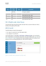
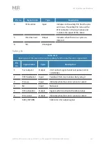
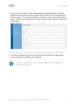
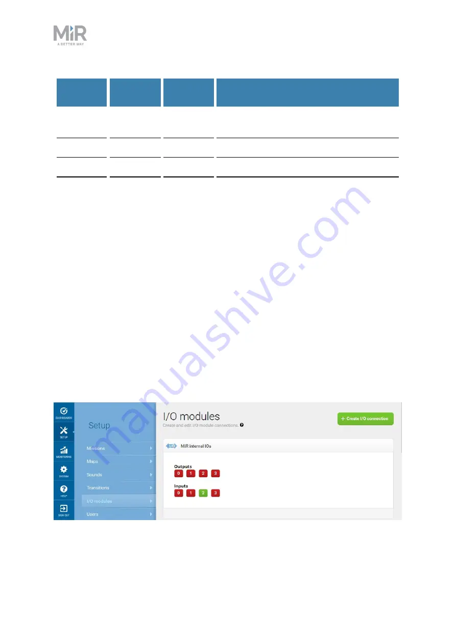
In the robot interface, under
Setup > I/O modules > MiR internal I/Os
, you can indirectly
control the GPIO pins—see what the internal I/Os in the robot interface do in
. Note that the input and output values in the interface do not
directly control the corresponding GPIO pins in the electrical interface.
Figure 18.2. Example of input 2 registered as active by the robot.