


4.6.6.1
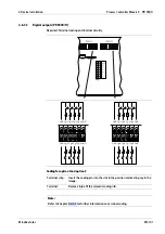
Digital inputs (PR 5900/13)
Depicted: Terminal coding and internal circuitry
CH 1
+ −
CH 2
+ −
CH 3
+ −
CH 4
+ −
2K
87
3V
0
+
12
V
DC
G
NDI
2K
87
3V
0
+
12
V
DC
G
NDI
2K
87
3V
0
+
12
V
DC
G
NDI
2K
87
3V
0
+
12
V
DC
G
NDI
CH 1
+ −
CH 2
+ −
CH 3
+ −
CH 4
+ −
2K
87
3V
0
+
12
V
DC
G
NDI
2K
87
3V
0
+
12
V
DC
G
NDI
2K
87
3V
0
+
12
V
DC
G
NDI
2K
87
3V
0
+
12
V
DC
G
NDI
Coding for option 1 and option 2
Terminal strip:
Insert the coding pin into the slot in the position marked in gray in the
image.
Terminal:
Remove (nip of) the relevant coding nib.
4 Device installation
Process Controller Maxxis 5 PR 5900
Minebea Intec
EN-91
Summary of Contents for Maxxis 5
Page 137: ......


