

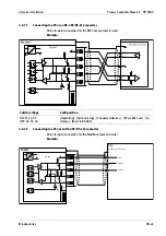


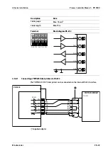


4.5.10 Internal digital inputs
4 active or passive opto-decoupled inputs are permanently built into the device for
process control.
Depending on the order, the hardware is factory-set to "passive" (order code "DE1") or
"active" (order code "DE2").
GNDA
CH 1
CH 2
CH 3
CH 4
+ −
+ −
+ −
+ −
Technical data
Description
Data
Connection
2 x terminal, 4-pin
Number of inputs
4 (CH1, CH2, CH3, CH4)
Input, active
Can be switched via a potential-free contact
Input voltage
Passive
Logic 0:
U
DC
= 0 to 5 V or open
Logic 1:
U
DC
= 10 to 28 V
An external power supply is required.
Input current
< 7 mA @ 24 V
< 3 mA @ 12 V
Protection against incorrect polarity
Input frequency
Max. 200 Hz (50% ratio)
Potential isolation
Active: jointly supplied via potential-free voltage.
Passive: via optocoupler
Cables
Screened
Connect the cable screen (wire gauge max. 1.5 mm
2
) to the
device screen clamping rail.
Cable length
Max. 50 m
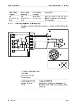
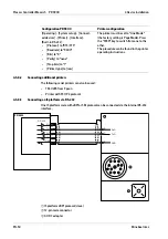
Coding pin
Is inserted in the position marked in gray in the image.
4 Device installation
Process Controller Maxxis 5 PR 5900
Minebea Intec
EN-55
Summary of Contents for Maxxis 5
Page 137: ......


