


5.2.3.3
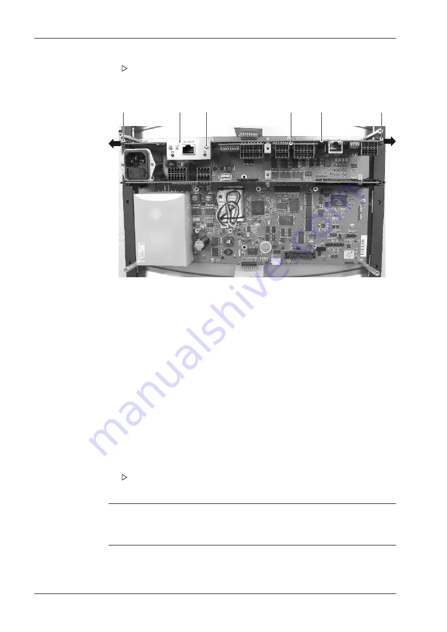
Optional and ieldbus cards
5
4
2
3
1
1
Note:
The installed plug-in cards can be displayed in the menu [Operating] - [System
information] - [Show HW options].
Once the plug-in cards have been replaced, the device will detect them
automatically.
1. Unplug all connectors. The cable screens and grounding/equipotential bonding
conductor can remain on the screen clamping rail.
2. Remove the screws to the housing.
3. Carefully remove the housing and set aside.
4. Open the bracket (1) and carefully remove the connection card (5).
5. Optional card (4): Remove the screw.
6. Fieldbus card (2): Unscrew both screws (3) to loosen the clamp.
7. Carefully loosen and remove the plug-in card from the pin strip.
8. Optional card (4): Insert the new plug-in card into the correct pin strip and ix to the
connection card (5) with the screw.
9. Fieldbus card (2): Insert the new plug-in card into the correct pin strip and ix to the
connection card (5) with both screws (3).
10. Replace the housing carefully. Ensure that the color-graphic display is connected
correctly.
11. Tighten the screws.
12. Plug all the connectors back in and switch the device back on.
Once the plug-in cards have been replaced, the device will detect them
automatically.
Process Controller Maxxis 5 PR 5900
5 Maintenance/repairs/soldering work/cleaning
EN-124
Minebea Intec
Summary of Contents for Maxxis 5
Page 137: ......


