PL-565
Accumass BW500
Page 103
P
ID Control
(constant speed) being fed from a pre-feeder some distance or more than a few
seconds process time from the scale.
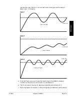
A properly set
D
term will make the initial oscillations around the setpoint smaller, as
in figure 6. A
D
term set too high induces high oscillations, as in figure 4. Omission of
the
D
term, or set too low, shows no effect on the system.
10.
The above closed loop cycling procedure allows ease in start up, but final
adjustments may be necessary in actual process operation.
Programming
The BW500 is software ready, however the controller function must be specifically
programmed in addition to programming of parameters P001 through P017.
The BW500 offers programming for two separate PID controls, 1 and 2. The
controller being programmed is identified by the suffix to the parameter number. e.g.
P400-01 indicates that PID for control system 1 is accessed.
Note:
All programming should be done in the PID manual mode.
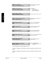
Access
P
P
P
P
P
P
P
P
4
4
4
4
4
4
4
4
0
0
0
0
0
0
0
0
0
0
0
0
0
0
0
0
-
-
-
-
-
-
-
-
0
0
0
0
0
0
0
0
1
1
1
1
1
1
1
1
P
P
P
P
P
P
P
P
I
I
I
I
I
I
I
I
D
D
D
D
D
D
D
D
S
S
S
S
S
S
S
S
y
y
y
y
y
y
y
y
s
s
s
s
s
s
s
s
t
t
t
t
t
t
t
t
e
e
e
e
e
e
e
e
m
m
m
m
m
m
m
m
E
E
E
E
E
E
E
E
S
S
S
S
S
S
S
S
e
e
e
e
e
e
e
e
l
l
l
l
l
l
l
l
e
e
e
e
e
e
e
e
c
c
c
c
c
c
c
c
t
t
t
t
t
t
t
t
:
:
:
:
:
:
:
:
0
0
0
0
0
0
0
0
-
-
-
-
-
-
-
-
O
O
O
O
O
O
O
O
f
f
f
f
f
f
f
f
f
f
f
f
f
f
f
f
,
,
,
,
,
,
,
,
1
1
1
1
1
1
1
1
-
-
-
-
-
-
-
-
M
M
M
M
M
M
M
M
a
a
a
a
a
a
a
a
n
n
n
n
n
n
n
n
u
u
u
u
u
u
u
u
a
a
a
a
a
a
a
a
l
l
l
l
l
l
l
l
,
,
,
,
,
,
,
,
2
2
2
2
2
2
2
2
-
-
-
-
-
-
-
-
A
A
A
A
A
A
A
A
u
u
u
u
u
u
u
u
t
t
t
t
t
t
t
t
o
o
o
o
o
o
o
o
0
0
0
0
0
0
0
0
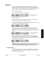
Off
disables the PID parameter set, P401 to P418. They are not accessible.
Manual
: the control output is the manual output P410.
Auto
: engages the PID controller function. This can also be done using the
key.
Notes:
•
For the mA output:
mA output 2 (P201-02) is normally reserved for controller 1. The signal is output
at terminals 1 and 2 on the mA I/O board.
mA output 3 (P201-03) is normally reserved for controller 2. The signal is output
at terminals 3 and 4 on the mA I/O board.
P
P
P
P
P
P
P
P
2
2
2
2
2
2
2
2
0
0
0
0
0
0
0
0
1
1
1
1
1
1
1
1
-
-
-
-
-
-
-
-
0
0
0
0
0
0
0
0
2
2
2
2
2
2
2
2
m
m
m
m
m
m
m
m
A
A
A
A
A
A
A
A
u
u
u
u
u
u
u
u
t
t
t
t
t
t
t
t
p
p
p
p
p
p
p
p
u
u
u
u
u
u
u
u
t
t
t
t
t
t
t
t
F
F
F
F
F
F
F
F
u
u
u
u
u
u
u
u
n
n
n
n
n
n
n
n
c
c
c
c
c
c
c
c
t
t
t
t
t
t
t
t
i
i
i
i
i
i
i
i
o
o
o
o
o
o
o
o
n
n
n
n
n
n
n
n
E
E
E
E
E
E
E
E
S
S
S
S
S
S
S
S
e
e
e
e
e
e
e
e
l
l
l
l
l
l
l
l
e
e
e
e
e
e
e
e
c
c
c
c
c
c
c
c
t
t
t
t
t
t
t
t
:
:
:
:
:
:
:
:
1
1
1
1
1
1
1
1
-
-
-
-
-
-
-
-
R
R
R
R
R
R
R
R
a
a
a
a
a
a
a
a
t
t
t
t
t
t
t
t
e
e
e
e
e
e
e
e
.
.
.
.
.
.
.
.
2
2
2
2
2
2
2
2
-
-
-
-
-
-
-
-
L
L
L
L
L
L
L
L
o
o
o
o
o
o
o
o
a
a
a
a
a
a
a
a
d
d
d
d
d
d
d
d
,
,
,
,
,
,
,
,
3
3
3
3
3
3
3
3
-
-
-
-
-
-
-
-
S
S
S
S
S
S
S
S
p
p
p
p
p
p
p
p
e
e
e
e
e
e
e
e
e
e
e
e
e
e
e
e
d
d
d
d
d
d
d
d
,
,
,
,
,
,
,
,
4
4
4
4
4
4
4
4
-
-
-
-
-
-
-
-
P
P
P
P
P
P
P
P
I
I
I
I
I
I
I
I
D
D
D
D
D
D
D
D
1
1
1
1
1
1
1
1
Note:
•
For the mA input:
mA input 1 is an external signal normally reserved for controller 1. The signal is
input at terminals 5 and 6 on the mA I/O board.
mA input 2 is an external signal normally reserved for controller 2. The signal is
input at terminals 7 and 8 on the mA I/O board.
Select manual to program PID
parameters.
Select the PID function.
Summary of Contents for ACCUMASS BW500
Page 1: ...ACCUMASS BW500 Instruction Manual PL 565 January 2001 CCUMASS BW500 33455650 Rev 1 2...
Page 6: ...Page 6 Accumass BW500 PL 565...
Page 12: ...Page 12 Accumass BW500 PL 565 Specifications...
Page 28: ...Page 28 Accumass BW500 PL 565 Installation...
Page 88: ...Page 88 Accumass BW500 PL 565 Parameters...
Page 94: ...Page 94 Accumass BW500 PL 565 Operation...
Page 106: ...Page 106 Accumass BW500 PL 565 PID Control...
Page 110: ...Page 110 Accumass BW500 PL 565 Batching...
Page 112: ...Page 112 Accumass BW500 PL 565 Certification...

