background image

PL-565

Accumass BW500

Page 111

Certification

Certification

For installations requiring trade certification, the BW500 provides a certification
compliance switch.

After certification of the installation has been obtained, the switch is set. The switch
must be positioned to the left to enable trade certification compliance.

When the switch is set for certification, editing of the parameter values, span
calibrations and totalizer resets are denied. Also, the maximum acceptable deviation
from one zero calibration to another is limited to an accumulated 

±

 2% of the initial

zero.

To set the certification switch, disconnect power before opening the enclosure lid.

  slide switch to the left position

  close the lid

 reconnect 

the 

power

Certification Printing

Certification printing is allowed if the following conditions are met:

  certification switch is set

  rate is below 2 %

  a communications port has been programmed for a printer

The printout must consist of the following:

Start Total:

End total of previous print

End Total:

Accumulated totalizer including Start Total

Net Total:

End total minus Start Total

Summary of Contents for ACCUMASS BW500

Page 1: ...ACCUMASS BW500 Instruction Manual PL 565 January 2001 CCUMASS BW500 33455650 Rev 1 2...

Page 2: ...n and in electronic version We encourage users to purchase authorized bound manuals or to view electronic versions as designed and authored by Siemens Milltronics Process Instruments Inc Siemens Millt...

Page 3: ...stant Speed No Sensor 22 Speed Sensor 22 Auxiliary Inputs 23 Auto Zero 23 RS 232 Port 1 23 Printers 23 Computers and Modems 24 Remote Totalizer 24 mA Output 1 24 Relay Output 25 RS 485 Port 2 25 Daisy...

Page 4: ...erivative PID Control Parameters P400 P418 73 Batch Control P560 P568 76 Totalization P619 P648 78 ECal Parameters P693 P698 81 Communication P750 P792 84 P750 P769 SmartLinx Module Specific Parameter...

Page 5: ...115 P771 protocol address 116 P772 Baud Rate 116 P773 Parity 116 P774 data bits 117 P775 stop bits 117 P778 modem attached 117 P779 modem idle time 117 P780 RS 232 transmission interval 118 P781 data...

Page 6: ...Page 6 Accumass BW500 PL 565...

Page 7: ...de Recalibration emphasizes how to optimize and maintain accurate operation of your weighing system through material tests and routine recalibrations Operation offers an overview of the BW500 features...

Page 8: ...Modbus protocol on the two RS 232 ports and the RS 485 port for communication to customer PLC or computer BW500 also supports Milltronics SmartLinx for communication with popular industrial communica...

Page 9: ...65 285 mm W x 209 mm H x 92 mm D 11 2 W x 8 2 H x 3 6 D polycarbonate Programming via local keypad and or Dolphin Plus interface Display illuminated 5 x 7 dot matrix liquid crystal display with 2 lin...

Page 10: ...sing Belden 8404 4 wire shielded 20 AWG or equivalent 150 m 500 ft max sensing Belden 9260 6 wire shielded 20 AWG or equivalent 300 m 1000 ft max two four load cells non sensing Belden 9260 6 wire shi...

Page 11: ...l optically isolated 0 1 of 20 mA resolution 200 S input impedance outputs 2 programmable 0 4 20 mA for PID control rate load and speed output optically isolated 0 1 of 20 mA resolution 750 S load max...

Page 12: ...Page 12 Accumass BW500 PL 565 Specifications...

Page 13: ...ow proper grounding procedures Dimensions 3 Non metallic enclosure does not provide grounding between connections Use grounding type bushings and jumpers Conduit entry area Recommend drilling the encl...

Page 14: ...ctions as outlined Installation 1 Isolate power and voltages applied to the BW500 2 Open the lid 3 Install the module by mating the connectors and secure in place using the two screws provided 4 Route...

Page 15: ...later date If you are ready to install your mA I O board please follow the instructions as outlined Installation 1 Isolate power and voltages applies to the BW500 2 Open the lid 3 Install the board by...

Page 16: ...upplied from SELV source in accordance with IEC 10101 1 Annex H Relay contact terminals are for use with equipment having no accessible live parts and wiring having insulation suitable for at least 25...

Page 17: ...l system capability Not all components or their maximum quantity may be required belt scale see Specifications speed sensor optional see Specifications customer remote totalizer mA input from customer...

Page 18: ...ade certification remove the jumpers BW500 terminal 11 12 and 13 14 run additional conductors from BW500 terminal 12 to scale red BW500 terminal 13 to scale blk If load cell wiring colours vary from t...

Page 19: ...tion remove the jumpers BW500 terminal 11 12 and 13 14 run additional conductors from BW500 terminal 12 to scale red BW500 terminal 13 to scale blk If load cell wiring colours vary from those shown or...

Page 20: ...11 12 and 13 14 run additional conductors from BW500 terminal 12 to scale red BW500 terminal 13 to scale blk If load cell wiring colours vary from those shown or if extra wires are provided consult Mi...

Page 21: ...rom BW500 terminal 12 to integrator terminal block EXC BW500 terminal 13 to integrator terminal block EXC For further connection information on specific LVDT s consult Milltronics Shields are common b...

Page 22: ...ill continue totalizing Speed Sensor MD Series RBSS or ENCODER Connect the BW500 terminal 16 to speed sensor terminal 2 for clockwise speed sensor shaft rotation 3 for counter clockwise speed sensor s...

Page 23: ...Inputs Customer dry contacts or open collector transistor output supplied as required Refer to P270 on page 67 for programming details Auto Zero prefeed activated dry contact Refer to Auto Zero on pa...

Page 24: ...on to a PC compatible computer or modem using no flow control typical configurations are DB 9 DB 25 Computer Modem Remote Totalizer supply 30V max supply 240V max mA Output 1 to customer instrumentati...

Page 25: ...umass BW500 Page 25 Installation Relay Output Relays shown in de energized state contacts normally open rated 5 A at 250 V non inductive RS 485 Port 2 Daisy Chain Terminal Device customer device custo...

Page 26: ...by a 15 A fuse or a circuit breaker in the building installation 2 A circuit breaker or switch in the building installation marked as the disconnect switch shall be in close proximity to the equipmen...

Page 27: ...ert it into the battery socket The memory battery see Specifications should be replaced every 5 years to insure memory back up during lengthy power outages An on board capacitor provides 20 minutes of...

Page 28: ...Page 28 Accumass BW500 PL 565 Installation...

Page 29: ...ode numerical and arithmetical keys View mode press to scroll through parameter list Press to initiate calibration Press to alternate between view and edit modes and enter parameter values clear entry...

Page 30: ...T T T T T T Te e e e e e e es s s s s s s st t t t t t t t R R R R R R R Re e e e e e e ef f f f f f f fe e e e e e e er r r r r r r re e e e e e e en n n n n n n nc c c c c c c ce e e e e e e e S S...

Page 31: ...0 0 0 0 00 0 0 0 0 0 0 0 0 0 0 0 0 0 0 00 0 0 0 0 0 0 0 K K K K K K K Kg g g g g g g g h h h h h h h h Press P P P P P P P P0 0 0 0 0 0 0 01 1 1 1 1 1 1 14 4 4 4 4 4 4 4 D D D D D D D De e e e e e e...

Page 32: ...L L Lo o o o o o o oa a a a a a a ad d d d d d d d C C C C C C C Ce e e e e e e el l l l l l l ll l l l l l l ls s s s s s s s V V V V V V V V E E E E E E E En n n n n n n nt t t t t t t te e e e e e...

Page 33: ...a a a a a at t t t t t t te e e e e e e e 0 0 0 0 0 0 0 0 0 0 0 0 0 0 0 00 0 0 0 0 0 0 0 t t t t t t t t h h h h h h h h Press P P P P P P P P0 0 0 0 0 0 0 01 1 1 1 1 1 1 11 1 1 1 1 1 1 1 D D D D D D...

Page 34: ...t t t th h h h h h h h V V V V V V V V E E E E E E E En n n n n n n nt t t t t t t te e e e e e e er r r r r r r r L L L L L L L Le e e e e e e en n n n n n n ng g g g g g g gt t t t t t t th h h h h...

Page 35: ...h h h h h h h ht t t t t t t t M M M M M M M MS S S S S S S S 1 1 1 1 1 1 1 1 V V V V V V V V E E E E E E E En n n n n n n nt t t t t t t te e e e e e e er r r r r r r r t t t t t t t te e e e e e e e...

Page 36: ...L L L L L Lo o o o o o o oa a a a a a a ad d d d d d d d C C C C C C C Ce e e e e e e el l l l l l l ll l l l l l l l B B B B B B B Ba a a a a a a al l l l l l l la a a a a a a an n n n n n n nc c c...

Page 37: ...i i i in n n n n n n ng g g g g g g g E E E E E E E E S S S S S S S Se e e e e e e el l l l l l l le e e e e e e ec c c c c c c ct t t t t t t t 1 1 1 1 1 1 1 1 A A A A A A A A B B B B B B B B 2 2 2 2...

Page 38: ...ccessful calibration ensure that the required criteria are met Refer to Calibration Criteria on page 139 Press Z Z Z Z Z Z Z Ze e e e e e e er r r r r r r ro o o o o o o o C C C C C C C Ca a a a a a a...

Page 39: ...n to the scale as instructed in the associate manuals Then start the conveyor Press S S S S S S S Sp p p p p p p pa a a a a a a an n n n n n n n C C C C C C C Ca a a a a a a al l l l l l l li i i i i...

Page 40: ...t t t t t t to o o o o o o o S S S S S S S St t t t t t t ta a a a a a a ar r r r r r r rt t t t t t t t Accepting the Span returns to start of Span A new Span can be performed or enter Run mode If ca...

Page 41: ...Ad d d d d d d dj j j j j j j ju u u u u u u us s s s s s s st t t t t t t t E E E E E E E E E E E E E E E En n n n n n n nt t t t t t t te e e e e e e er r r r r r r r N N N N N N N Ne e e e e e e ew...

Page 42: ...form a manual span adjust Note Test weights are NOT used during material tests There are two methods of executing the manual span adjust Change and Material Test Change based on the material test the...

Page 43: ...a at t t t t t t te e e e e e e ed d d d d d d d e e e e e e e er r r r r r r rr r r r r r r ro o o o o o o or r r r r r r r 0 0 0 0 0 0 0 0 0 0 0 0 0 0 0 00 0 0 0 0 0 0 0 Press P P P P P P P P5 5 5 5...

Page 44: ...t t t t t t te e e e e e e er r r r r r r ri i i i i i i ia a a a a a a al l l l l l l l T T T T T T T Te e e e e e e es s s s s s s st t t t t t t t 9 9 9 9 9 9 9 96 6 6 6 6 6 6 64 4 4 4 4 4 4 4 0 0...

Page 45: ...a a a a a at t t t t t t ti i i i i i i io o o o o o o on n n n n n n n 0 0 0 0 0 0 0 0 0 0 0 0 0 0 0 02 2 2 2 2 2 2 2 P P P P P P P Pr r r r r r r re e e e e e e es s s s s s s ss s s s s s s s E E E...

Page 46: ...P P P P P P P Pr r r r r r r re e e e e e e es s s s s s s ss s s s s s s s E E E E E E E EN N N N N N N NT T T T T T T TE E E E E E E ER R R R R R R R t t t t t t t to o o o o o o o a a a a a a a ac...

Page 47: ...ess than an accumulated 2 from the last operator initiated zero the auto zero is accepted If the deviation is greater than an accumulated 2 an error message is displayed The error message is cleared a...

Page 48: ...te e e e e e e ed d d d d d d d B B B B B B B Be e e e e e e el l l l l l l lt t t t t t t t s s s s s s s sp p p p p p p pe e e e e e e ee e e e e e e ed d d d d d d d i i i i i i i is s s s s s s s...

Page 49: ...I I I I In n n n n n n ni i i i i i i it t t t t t t ti i i i i i i ia a a a a a a al l l l l l l l S S S S S S S Sp p p p p p p pa a a a a a a an n n n n n n n C C C C C C C Ca a a a a a a al l l l l...

Page 50: ...C C C C Co o o o o o o ou u u u u u u un n n n n n n nt t t t t t t t 4 4 4 4 4 4 4 41 1 1 1 1 1 1 19 9 9 9 9 9 9 90 0 0 0 0 0 0 0 Multispan The BW500 offers a multispan function which allows the BW50...

Page 51: ...T T T T T T Te e e e e e e es s s s s s s st t t t t t t t L L L L L L L Lo o o o o o o oa a a a a a a ad d d d d d d d W W W W W W W We e e e e e e ei i i i i i i ig g g g g g g gh h h h h h h ht t t...

Page 52: ...x x x x xi i i i i i i il l l l l l l li i i i i i i ia a a a a a a ar r r r r r r ry y y y y y y y I I I I I I I In n n n n n n np p p p p p p pu u u u u u u ut t t t t t t t F F F F F F F Fu u u u u...

Page 53: ...F F F F F F Fa a a a a a a ac c c c c c c ct t t t t t t to o o o o o o or r r r r r r ri i i i i i i in n n n n n n ng g g g g g g g i i i i i i i in n n n n n n n p p p p p p p pr r r r r r r ro o...

Page 54: ...n order to resolve the non linearity by improved installation or repair If it is determined that the non linearity is due to the weighing application and not the actual belt scale apply linearization...

Page 55: ...aggerated for emphasis The material tests should be run at same belt speed representative of normal operation in this case 1 2 m s For each rate record the corresponding load value by scrolling to the...

Page 56: ...ion is required usually at a low load value In the prior example if compensation was only required at 6 94 kg m the programming could be as follows Compensation is optimized by establishing the next l...

Page 57: ...alue P000 Security Lock Locks out the program editor so that parameter values for P001 through P999 cannot be changed This however does not prevent the access to the parameters for viewing Programming...

Page 58: ...sent a material load weight chain or electronic weight the weight that is supplied specific to the scale chain optional sized specific to scale and conveyor electronic calibration based on automatic c...

Page 59: ...kg LT 2240 lb T 2000 lb P008 Date Enter the current date in yyyy mm dd format where yyyy year mm month 01 12 dd day 01 31 e g 1999 03 19 March 19 1999 P009 Time Enter the current time in hh mm ss 24...

Page 60: ...ad to be referenced when performing a span f 0 00 Load units are lb ft if the imperial system of measurement has been selected P004 1 kg m if the metric system of measurement has been selected P004 2...

Page 61: ...z at 1 Hz it takes 1 s before defaulting to 0 speed 2 2 Hz f at 2 Hz it takes 0 5 s before defaulting to 0 speed P080 Damping Display P080 01 Rate P080 02 Load P080 03 Speed Sets the speed of response...

Page 62: ...PID 02 setpoint deviation 7 pre warn 8 setpoint valid only if PID system P400 is enabled valid only if batch function P560 is enabled P101 High Alarm Deviation Alarm High Alarm f 100 For relay functi...

Page 63: ...ale or for deviation alarm enter of setpoint Note Not applicable if P100 4 7 or 8 P118 Relay Logic Sets the logic applied to relays to determine their open or closed state Power Failure The relays on...

Page 64: ...verride This function allows the user to simulate an alarm condition on or off which will override normal operation until P119 setting is returned to normal Values P119 Condition Display alarm field 0...

Page 65: ...A output PID control 1 1 2 PID control 2 2 3 P200 mA Output Range Sets the mA range for the output selected outputs 1 to 3 P200 01 to 03 Entry 1 0 20 mA 2 4 20 mA f P201 mA Output Function Assigns the...

Page 66: ...the output to agree with a milliammeter or other external mA input device Scroll the trim value up or down P215 20 mA Output Trim Trims the 20 mA output level for the output selected outputs 1 to 3 P2...

Page 67: ...input P270 Auxiliary Input Function Selects the auxiliary input function for the input selected inputs 1 to 5 P270 01 to 13 Function Symbol Description alternate display momentary closure of the input...

Page 68: ...ltispan operation the auxiliary input contact state determines the multispan number equivalent to P365 Input 1 is reserved for multispan 1 and 2 selection Input 2 is reserved for multispan 3 and 4 sel...

Page 69: ...bration Security This parameter provides additional security to the global lock P000 zero span reset T1 0 no additional security f 1 in addition to P000 lock no span 2 in addition to P000 no zero and...

Page 70: ...liary Input Function 6 on page 67 P367 Direct Zero Entry Directly enters the zero reference count Direct entry is intended for use when replacing software or hardware and it is not convenient to perfo...

Page 71: ...ave deviated beyond the zero limit P370 f 1 Note Refer to Initial Zero on page 46 for execution P388 Initial Span Resets the initial span for the span selected multispan 1 to 8 P388 01 to 08 The initi...

Page 72: ...rizer Enables or disables the linearization function Entry 0 off f 1 on P391 Linearizer Load Points Enters the load values in units of P017 for the point selected points 1 to 5 P391 01 to 05 f 0 00 P3...

Page 73: ...Normally the controller is updated each time the process value is updated every 300 ms However in unstable or slow reacting systems the controller update can be programmed to update on a multiple of...

Page 74: ...e feed forward term 0 000 to 1 000 P410 Manual Mode Output Displays the percentage output value P410 01 or 02 for the corresponding PID system 1 or 2 When the PID system is in manual this is the value...

Page 75: ...ngineering units for the corresponding PID system 1 or 2 For the external process variable the setpoint is shown is If the setpoint is external P414 1 or 2 then this parameter displays the setpoint va...

Page 76: ...Enables or disables the pre warn function associated with batch control warning that the batch is nearing completion Entry 0 off f 1 on P567 Batch Pre Warn Setpoint Sets the setpoint for the pre warn...

Page 77: ...h Pre Act Amount Enter a value to make the setpoint relay change state at a known value lower than the setpoint P564 e g Setpoint 1000 Manual Pre Act 50 The setpoint relay will activate when the batch...

Page 78: ...ameter sets the resolution of the totalizer selected Totalizers are 01 totalizer 1 02 totalizer 2 03 verification totalizer 04 material test totalizer 05 batch totalizer Entry 1 0 001 one thousandth 2...

Page 79: ...nit f 5 10 x ten 6 100 x hundred 7 1000 x thousand P643 External Contact Closure Sets the duration of the contact closure in ms for the external totalizer selected totalizers 1 and 2 P643 01 or 02 f 3...

Page 80: ...ign data sheet or speed sensor pulses per revolution pulley circumference m or ft revolution 2 sensor data the selection forwards the program to P691 and P692 for entry of the required sensor data for...

Page 81: ...the selected cell f 1 0 01 load cell A 02 load cell B 03 load cell C 04 load cell D applicable only if P693 3 Enter the value in the units corresponding to the scale selection e g in kg if P693 1 or...

Page 82: ...nation Enters the inclination or declination angle of the conveyor at the point where the belt scale is installed f 0 0000 Enter the inclination in degrees Upon entry display jumps to P017 to display...

Page 83: ...39 Time Zone The offset from Greenwich mean time GMT of local time This parameter does not affect any timed events because all times are local It can be accessed by a remote computer for synchronizati...

Page 84: ...s are specific to programming of the BW500 communication ports Refer to Communications for a listing and description of these parameters P790 SmartLinx Error Status Displays the results of ongoing har...

Page 85: ...asurement A test value can be entered and the displayed value is transmitted to the output Upon returning to the run mode the parameter assumes the actual mA output level f 0 Use the up and down to sc...

Page 86: ...P949 Diagnostic Error Testing Enables or disables diagnostic error checking for memory load cell and zero speed f 0 Entry 0 disable 1 enable Refer to Troubleshooting on page 137 P950 Zero Register Re...

Page 87: ...PL 565 Accumass BW500 Page 87 Parameters P999 Master Reset Resets parameters and totalizers to their factory setting f 0 Enter 9 to execute the reset...

Page 88: ...Page 88 Accumass BW500 PL 565 Parameters...

Page 89: ...t terminals 17 18 The speed constant P015 defaults to jumpered This contact should change to open when the conveyor is idle to prevent errant totalization Refer to Specifications on page 9 and Install...

Page 90: ...e signal deviation is greater than 10 of the reference value the signal will jump immediately to that new value This value will be the new reference For example A conveyor is running material at 3 t h...

Page 91: ...PID control loop 2 Input The optional mA I O board provides two mA inputs programmable as inputs 1 and 2 If programmed for PID control generally input 1 is assigned to PID control loop 1 and input 2 i...

Page 92: ...m on is with relay de energized Totalization The totalization function is based on the internal rate mass per unit time signal proportional to belt speed and load on the associated belt scale It is no...

Page 93: ...automatically calculated upon entry of the design rate P011 and remote totalizer P638 parameters so that the duration of contact closure allows the relay response to track the total up to 150 of the...

Page 94: ...Page 94 Accumass BW500 PL 565 Operation...

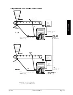
Page 95: ...n to the controlled flow rate In order for the BW500 to operate as a controller the following must be addressed hardware connections setup and tuning programming Hardware In order for the BW500 to ope...

Page 96: ...or speed load control output P201 02 4 optional remote setpoint rate P255 01 1 belt scale speed sensor speed load control output P201 02 4 optional remote setpoint load P255 01 1 PID 1 process value s...

Page 97: ...speed load SLAVE speed MASTER control output rate P201 02 4 remote ratio setpoint rate P255 01 1 P418 01 to suit control output P201 02 4 rate P201 01 1 remote setpoint rate P255 01 1 load speed sens...

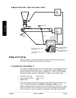
Page 98: ...ble input range 0 000 to 2 000 typical operating range 0 300 to 0 600 default value 0 400 The control output cannot reach the setpoint using only the P term Since the P term acts on the difference bet...

Page 99: ...an make the system unstable A derivative term is needed to influence the control output as the process variable approaches the set point Derivative Control Pre Act or Rate D The D term on the BW500 in...

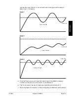
Page 100: ...D terms is essential to system operation and optimum performance from the feeder The recommended procedures for tuning the PID control terms at initial start up are described in this section Initial S...

Page 101: ...he P term value is set to give the control output of the BW500 consistent oscillation and the error is at its minimum turn the feeder off 6 The I term value can now be set Begin by entering the defaul...

Page 102: ...applications The purpose of the D term is to anticipate where the process is heading by looking at the time rate and direction of change of the process variable The D term becomes very useful in appl...

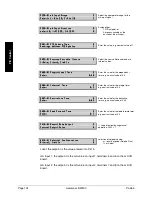
Page 103: ...l l l l 2 2 2 2 2 2 2 2 A A A A A A A Au u u u u u u ut t t t t t t to o o o o o o o 0 0 0 0 0 0 0 0 Off disables the PID parameter set P401 to P418 They are not accessible Manual the control output i...

Page 104: ...0 0 0 0 0 06 6 6 6 6 6 6 6 0 0 0 0 0 0 0 01 1 1 1 1 1 1 1 I I I I I I I In n n n n n n nt t t t t t t te e e e e e e eg g g g g g g gr r r r r r r ra a a a a a a al l l l l l l l T T T T T T T Te e e...

Page 105: ...M M M M Ma a a a a a a as s s s s s s st t t t t t t te e e e e e e er r r r r r r r o o o o o o o ou u u u u u u ut t t t t t t tp p p p p p p pu u u u u u u ut t t t t t t t 1 1 1 1 1 1 1 10 0 0 0 0...

Page 106: ...Page 106 Accumass BW500 PL 565 PID Control...

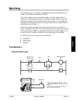
Page 107: ...Another relay can be programmed as a pre warn alarm P100 7 to alert the process that batch end is near The relay is actuated when the material total reaches the pre warn setpoint P567 at some practica...

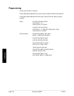
Page 108: ...nction select relay 1 5 select function 7 pre warn access P100 relay function select relay 1 5 other than the pre warn relay select function 8 setpoint batch operation access P560 batch mode control s...

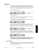
Page 109: ...M M M 1 1 1 1 1 1 1 1 The process continues and when the batch total reaches the batch setpoint the alarm event is displayed and the assigned relay is actuated contact opened Typically the relay cont...

Page 110: ...Page 110 Accumass BW500 PL 565 Batching...

Page 111: ...lso the maximum acceptable deviation from one zero calibration to another is limited to an accumulated 2 of the initial zero To set the certification switch disconnect power before opening the enclosu...

Page 112: ...Page 112 Accumass BW500 PL 565 Certification...

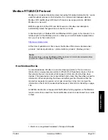
Page 113: ...a SCADA system using a serial device such as radio modems leased lines or dial up modems The BW500 supports two protocols Dolphin and Modbus Dolphin is a proprietary Milltronics protocol designed to b...

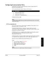
Page 114: ...nnection There are three serial communication ports on the BW500 Port Description 1 RS 232 terminals 31 to 34 2 RS 485 terminals 41 to 46 3 RS 232 RJ 11 modular telephone jack Refer to the Installatio...

Page 115: ...0 01 to 03 The BW500 supports Milltronics proprietary Dolphin data format plus the internationally recognized Modbus standard in both ASCII and RTU formats It also supports direct connection of a prin...

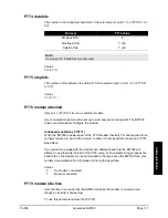
Page 116: ...dresses Do not use the value 0 for Modbus communications as this is the broadcast address and is inappropriate for a slave device Values 0 to 9999 f 1 P772 Baud Rate The communication rate with the ma...

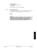
Page 117: ...automatically configure the modem Autobaud enabled by P778 1 When the BW500 is powered up or the P779 Modem Inactivity Timeout expires three carriage returns are sent to the modem to allow it to set...

Page 118: ...hat P779 is set longer than the standard polling time of the connected master device 0 disables the inactivity timer Values 0 9999 0 f 1 P780 RS 232 transmission interval Note Applicable only to ports...

Page 119: ...amming control either locally through the keypad or Dolphin Plus P770 1 or remotely through Modbus protocol P770 2 or 3 or SmartLinx Entry 0 local 1 remote Warning When a SmartLinx card is installed a...

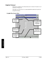
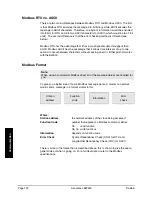
Page 120: ...of this protocol is to connect the BW500 to Milltronics Dolphin Plus configuration software Dolphin Plus Screen Shot Tabs show groups of parameters Parameters have roll overs which show number Paramet...

Page 121: ...s communications products Modbus protocol Note Milltronics does not own the Modbus RTU protocol All information regarding that protocol is subject to change without notice How Modbus Works As mentione...

Page 122: ...between characters without causing an error Either protocol works with the BW500 Modbus Format Note When using a commercial Modbus driver all of the message details are handled for you To give you a b...

Page 123: ...ion brief description or title of associated register Start provides the starting address for the register s where the parameter values are to be read from or written to Number R the number of registe...

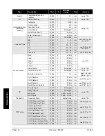
Page 124: ...e p 128 Command Control 41 022 1 bit mapped r w see p 129 Multi Span Selection 41 024 1 1 4 r w see p 50 and P365 on pg 70 PID 1 Setpoint 41 040 2 32 bits r w PID 2 Setpoint 41 042 2 32 bits r w see P...

Page 125: ...ers that are used for reading and writing parameter values to and from the BW500 The first three registers are always unsigned integers representing parameters and index values The second three regist...

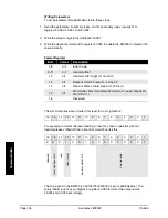
Page 126: ...r Float 1 14 0 1 Read or Write of data Read 0 Write 1 15 0 1 Word order Most Significant Word first 0 Least Significant Word first 1 16 Reserved The bits listed above are in order from least to most s...

Page 127: ...he format word This allows for 256 potential error codes Currently the BW500 has two error codes available Values Description 0 No error 1 Data not available as percent available as units 2 255 Reserv...

Page 128: ...he state should be checked to verify any device commands Bit Description Bit Clear 0 Bit Set 1 1 PID 1 Mode Manual Auto 2 PID 1 Freeze No Yes 3 PID 1 Setpoint Source Local Remote 4 PID 2 Mode Manual A...

Page 129: ...Freeze No Yes 3 PID 1 Setpoint Source Local Remote 4 PID 2 Mode Manual Auto 5 PID 2 Freeze No Yes 6 PID 2 Setpoint Source Local Remote 7 Zero No change Start 8 Span No change Start 9 Reset Totalizer 1...

Page 130: ...value and mA input value The mA I O are mapped into the respective input and output registers Input Register Output Register 1 R41 090 1 R41 110 2 R41 091 2 R41 111 3 R41 112 For 0 to 20 mA I O the re...

Page 131: ...SW and the second word register is the least significant word LSW For example if we read R41 431 as a 32 bit the 32 bits would look like the following R41 431 R41 432 16 MSB 1 16 LSB 1 32 32 bit integ...

Page 132: ...ccumass BW500 PL 565 Communication Number Text Message as displayed on LCD 30008 pass 30009 fail 30010 hold 30011 lo 30012 hi 30013 de 30014 en 32768 value is less than 20 000 32767 value is greater t...

Page 133: ...types but all use radio frequencies for transmitting the information Fiber optic uses a fiber optic line to connect the two modems Each type of modem and each model have various characteristics Befor...

Page 134: ...ds Answer Delay 30 seconds Inter character delay 55 ms Slave Modem auto answer on dip switch load factory default dip switch no flow control dip switch baud rate 9600 10 data bits probably the default...

Page 135: ...wable value for the slave 04 Slave Device Failure An unrecoverable error occurred while the slave was attempting to perform the requested action 05 Acknowledge The slave has accepted a request and is...

Page 136: ...e However the current value will not reflect the desired new value If the user writes a read only register then the value will be ignored and no error response will be made However the current value w...

Page 137: ...cate with it 4 Finally if you should check that the port you are using on the computer Sometimes trying a different Modbus driver will solve the problem An easy stand alone driver called ModScan32 is...

Page 138: ...s applied during span 221 Span out of range Span deviation 12 5 Consider an initial zero P377 Refer to Initial Zero on page 46 222 Zero out of range Zero deviation minimum limit Consider an initial Sp...

Page 139: ...ncluded in the parameter file However new zero and span calibrations should be done regardless and as soon as possible to insure operating accuracy Calibration Criteria Zero belt must be empty Run the...

Page 140: ...Page 140 Accumass BW500 PL 565 Appendices...

Page 141: ...c 1954 Technology Drive P O Box 4225 Peterborough ON Canada K9J 7B1 Tel 705 745 2431 Fax 705 741 0466 www milltronics com Siemens Milltronics Process Instruments Inc 2000 Subject to change without pri...

Reviews: