background image

OM-257 675 Page 36

9-3. Automated Welding Equipment Recommendations

Planning proper layout and routing of welding cables and control cables should be considered when setting up automated equipment.

1.

Whenever possible all cables should be routed out of the path of moving equipment.

2.

Cable installation in a stationary position will decrease the likelihood of wires breaking down in the cable.

3.

Cables that are moving will breakdown over time. This time can be increased by making sure there are no stress points when installing cables,

and deciding how and where to tie cables down.

4.

If at all possible, do not route weld cables and control cables together. Leave as much space as reasonable between the weld cables and any

other control cables. Welding generates electrical noise which is present on the weld cables (see 9-9 for grounding information).

9-4. Process Considerations

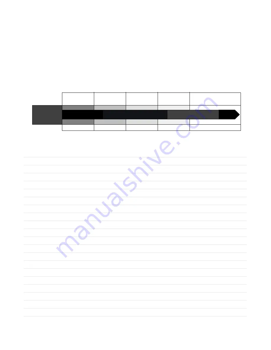
To obtain the most performance from the welding equipment, it is important to use the right transfer mode for the application. There are no hard and fast

rules, but there are general guidelines to follow when making a selection. The transfer modes available depend on the power source being used. The

possible transfer modes are as follows: Short Arc, Spray, Pulsed Spray, Accu-pulse, and RMD (Regulated Metal Deposition).

Weld Puddle

Control

Process

Standard

Spray

Pulsed

Spray

Accu-pulse

t

Standard

Short Circuit

RMD

t

 Regulate Metal

Deposition

Flat/Horizontal

All Position Performance

Thin Material/Gap Filling

Note: To achieve optimum performance, 4/0 welding secondary cable is recommended and the supplied work sense lead must be

connected as close to the arc as possible.

Notes

Summary of Contents for Auto-Axcess E Digital

Page 1: ...AW Welding Automatic Welding Automatic Welding Interface And Arc Welding Power Source File Advanced Manufacturing Systems Visit our website at www MillerWelds com ams Scan this tag with your mobile de...

Page 2: ...ntinue the tradition They re just as committed to providing equipment and service that meets the high standards of quality and value established in 1929 This Owner s Manual is designed to help you get...

Page 3: ...O AXCESS E 300 DIGITAL 13 4 1 Serial Number And Rating Label Location 13 4 2 Power Source Functionality 13 4 3 Unit Specifications 13 4 4 Dimensions And Weight 13 4 5 Duty Cycle And Overheating 14 4 6...

Page 4: ...ble Connections For Multiple Welding Arcs 40 9 9 Earth Grounding 43 9 10 30 Points Of Mechanics In MIG Welding 45 9 11 Typical Robot Signals 46 9 12 ADAM 6050 47 9 13 Loading The ADAM 6050 Program 47...

Page 5: ...k Diagnostic LEDs 102 13 4 Diagnostic LEDs On E Module Board Stack 103 13 5 Network And Module Status LEDs 104 13 6 Troubleshooting 105 13 7 Check Web Message Display 105 13 8 Software Error Message D...

Page 6: ......

Page 7: ...neeling or lying or when there is a high risk of unavoid able or accidental contact with the workpiece or ground For these conditions use the following equipment in order presented 1 a semiautomaticDC...

Page 8: ...ared according to AWS F4 1 and AWS A6 0 see Safety Standards D Do not weld where the atmosphere may contain flammable dust gas or liquid vapors such as gasoline D Connect work cable to the work as clo...

Page 9: ...NG PARTS can injure D Keep away from moving parts such as fans D Keep all doors panels covers and guards closed and securely in place D Have only qualified persons remove doors panels covers or guards...

Page 10: ...NFPA Standard 51B from National Fire Protection Association Quincy MA 02269 phone 1 800 344 3555 website www nfpa org OSHA Occupational Safety and Health Standards for General Indus try Title 29 Code...

Page 11: ...UNIQUE MENT si le proc d de soudage le demande D Si l utilisation d une source lectrique courant lectrique s av re n cessaire se servir de la fonction de t l commande si l appareil en est quip D D aut...

Page 12: ...nts et les tincelles pr venir toute personne sur les lieux de ne pas regarder l arc D Porter un quipement de protection pour le corps fait d un mat riau r sistant et ignifuge cuir coton robuste laine...

Page 13: ...ci s en bon tat D Tourner le dos la sortie de vanne lors de l ouverture de la vanne de la bouteille Ne pas se tenir devant ou derri re le r gulateur lors de l ouverture de la vanne D Le couvercle du d...

Page 14: ...es de rechange recommand es par le constructeur D Effectuer l entretien en respectant les manuels d utilisation les normes industrielles et les codes nationaux d tat et locaux LE RAYONNEMENT HAUTE FR...

Page 15: ...l Fire Protection Association Quincy MA 02269 phone 1 800 344 3555 website www nfpa org OSHA Occupational Safety and Health Standards for General Indus try Title 29 Code of Federal Regulations CFR Par...

Page 16: ...OM 257 675 Page 10...

Page 17: ...llaneous Symbols And Definitions Some symbols are found only on CE products Three Phase Static Frequency Converter Trans former Rectifier 1 Single Three Phase Static Frequency Converter Trans former R...

Page 18: ...OM 257 675 Page 12 Notes...

Page 19: ...Voltage DC Amperes Input At Rated Load Output 60 Hz Single Phase Three Phase Input kVA Input KW 208 V 230 V 380V 400V 460 V 575 V Single Phase 175 A 22 8 V DC 100 Duty Cycle 10 44 Standard 50 1400 ipm...

Page 20: ...y Overheating 0 15 A V OR Reduce Duty Cycle Minutes duty1 4 95 178 651 Continuous Welding 100 Duty Cycle At 225 Amperes 60 Duty Cycle At 300 Amperes 6 Minutes Welding 4 Minutes Resting 4 6 Volt Ampere...

Page 21: ...ass RK5 See UL 248 3 Normal Operating general purpose no intentional delay fuses are UL class K5 up to and including 60 amps and UL class H 65 amps and above 4 Conductor data in this section specifies...

Page 22: ...OM 257 675 Page 16 Notes...

Page 23: ...t Power Rated Welding Output Voltage Range Wire Feed Speed Range Wire Diameter Range Max Open Circuit Voltage DC Amperes Input At Rated Load Output 60 Hz Three Phase Input kVA Input KW 208 V 230 V 380...

Page 24: ...ty Overheating 0 15 A V OR Reduce Duty Cycle Minutes duty1 4 95 220 485 A Continuous Welding 100 Duty Cycle At 450 Amperes 60 Duty Cycle At 580 Amperes 6 Minutes Welding 4 Minutes Resting 5 6 Volt Amp...

Page 25: ...Recommended Standard Fuse Rating In Amperes1 Time Delay Fuses 2 60 60 35 35 30 25 Normal Operating Fuses 3 80 70 45 45 35 30 Min Input Conductor Size In AWG 4 6 8 8 10 10 12 Max Recommended Input Cond...

Page 26: ...OM 257 675 Page 20 Notes...

Page 27: ...e Wire Feed Speed Range Wire Diameter Range Max Open Circuit Voltage DC Amperes Input At Rated Load Output 60 Hz Three Phase Input KVA Input KW IP Rating 230 V 400V 460 V 575 V Three Phase 675 A 44 V...

Page 28: ...can damage unit and void warranty Overheating 0 15 A V OR Reduce Duty Cycle Minutes duty1 4 95 206 789 A Continuous Welding 100 Duty Cycle At 675 Amperes 6 6 Volt Ampere Curves va_curve1 4 95 221 502...

Page 29: ...44 35 Max Recommended Standard Fuse Rating In Amperes 1 Time Delay Fuses 2 110 60 50 40 Normal Operating Fuses 3 125 80 70 50 Min Input Conductor Size In AWG 4 3 6 8 8 Max Recommended Input Conductor...

Page 30: ...OM 257 675 Page 24 Notes...

Page 31: ...t sold All rights reserved SECTION 8 GENERAL INSTALLATION Appearance of actual unit may vary from unit shown in manual 8 1 Selecting A Location loc_2 3 96 Ref 249 889 B Do not stack units Beware of ti...

Page 32: ...Robot DeviceNet Cable 7 Gas And Motor Control Cable 8 Welding Power Source Interface Unit 9 Negative Weld Cable 10 Workpiece 11 Voltage Sensing Lead Recommendedfor Accu pulse and RMD Positive voltage...

Page 33: ...hase power Maximum output from RC2 is limited by supplementary protector CB1 to 10 amps 2 Supplementary Protector CB1 3 Supplementary Protector CB2 CB1 protects 115 volt receptacle RC2 from overload I...

Page 34: ...olts S Digital output 5 DO5 T Digital input 7 DI7 8 7 Touch Sensor Operation The touch sensor feature allows the robot to locate a weldment using the wire feed system and welding power source The weld...

Page 35: ...or Control Receptacle Functions D H B E K F J A C G Ref 258 604 B Socket Socket Information A Not used B Motor negative C Tach A D Motor positive E Tach common F Gas valve G Electrode sense H Tach 5 v...

Page 36: ...inal and bus terminal on PC2 as shown until voltage drops to near 0 zero volts Measure input capacitor voltage on both inverter assemblies before proceeding 3 Typical Bleeder Resistor An example of a...

Page 37: ...General OM 257 675 Page 31 Notes...

Page 38: ...ut5 2013 04 Ref 803 766 C Ref 249 744 A 258 604 B 218 005 A Tools Needed 5 16 in Route ground conductor through current transducer to ground terminal Route input power cable through tubing inside unit...

Page 39: ...per amperage capacity and correct hole size Welding Power Source Input Power Connections 2 Strain Relief Install strain relief of proper size for unit and input conductors Route conductors cord throug...

Page 40: ...2 to select proper cable size 1 Positive Weld Output Terminal 2 Negative Weld Output Terminal Connect positive weld cable to Positive weld terminal and negative cable to Negative weld terminal 3 Weld...

Page 41: ...0 70 3 0 95 4 0 120 2 ea 2 0 2x70 2 ea 3 0 2x95 2 ea 3 0 2x95 2 ea 4 0 2x120 400 1 0 60 2 0 70 3 0 95 4 0 120 2 ea 2 0 2x70 2 ea 3 0 2x95 2 ea 4 0 2x120 2 ea 4 0 2x120 500 2 0 70 3 0 95 4 0 120 2 ea 2...

Page 42: ...other control cables Welding generates electrical noise which is present on the weld cables see 9 9 for grounding information 9 4 Process Considerations To obtain the most performance from the welding...

Page 43: ...tory performance with a standard welding circuit connection The length of a welding circuit is determinedas follows Welding Circuit Electrode Cable Length ECL Work Cable Length WCL Workpiece Length WL...

Page 44: ...cable and compensates for voltage drop in all semi automatic processes when the Vsense option is On The work sense lead connects to the Axcess welding power source 4 pin connector located above the ne...

Page 45: ...ielding gas regulator and shielding gas connection for each welding gun Arc blow is the deflection of a welding arc from its normal path due to magnetic forces It will adversely affect the appearance...

Page 46: ...a bad setup due to sensing leads being directly in the current flow path of the welding arc Interaction between welding circuits will affect voltage drop in the workpiece The voltage drop across the...

Page 47: ...Sensing Lead 6 Robot 7 Workpiece This arrangement is a better setup for supporting separate voltage feedback to the welding power sources The most accurate voltage sensing may not be achieved due to...

Page 48: ...Work Cable 5 Voltage Sensing Lead 6 Robot 7 Workpiece This arrangement is the best setup for proper voltage sensing at the workpiece Voltage feedback to the welding power sources will more accurate a...

Page 49: ...nd Earth Ground Being Measured 100W Light Bulb 110 Volts AC Neutral 1 Volt 1 W V Measuring Facility Earth Ground Resistance The resistance of an earth ground can be measured using a 100W light bulb an...

Page 50: ...g Conduit Isolate It From Robot Control Cabinet Existing Input Power Supply Ground Make Ground Lead 5 ft 1 5 m To 10 ft 3 m Longer And Coil It Inside Robot Control 10 ft 3 m Minimum Work Weld Cable Wo...

Page 51: ...replace if necessary 14 Check placement of payoff pack or drum for smooth feed path 15 Inspect condition and routing of input conduit 16 Check installation of quick connect coupling at rear of wire dr...

Page 52: ...n selected mode of transfer Voltage MIG Trim M technology pulse Arc adjust Accu pulse basically arc length control C Often Used Robot Signals 1 Standby signal this means power source is ready to weld...

Page 53: ...verter that is used for Centerpoint operation when connected into a DeviceNet communication system The ADAM 6050 is not needed for Ethernet communication systems 9 13 Loading The ADAM 6050 Program Ins...

Page 54: ...Adam NET Utility exe Completethe installation connect the ADAM 6050 to appropriate power 10 30 VDC and your computer with an Ethernet cable then run the program just installed Adam Net Utility Right c...

Page 55: ...he ADAM 6050 from the factory is 10 0 0 1 You may have to set a static IP on your PC in the 10 0 0 x range and restart the program to get the block to appear If your PC connection to the ADAM 6050 is...

Page 56: ...257 675 Page 50 Click on the 6050 symbol and you will see the following screen Click on the 6050 symbol and then click on the sign next to it to expand the list Click on DI 0 to get the following scre...

Page 57: ...k on the Network tab and set the IP address to be compatible with the power source If you are using the Axcess E port A direct connect use 169 254 0 1 If you are connecting through a switch get an app...

Page 58: ...as possible S Turn off the Part Start S Wait for Weld Monitor Error OFF part error optional as required for each installation In the case where it is preferable to have the robot send the weld number...

Page 59: ...t 2 Input 3 Part Weld Select 3 Input 4 Part Weld Select 4 Input 5 Part Weld Select 5 Input 6 Part Weld Select 6 Input 7 Part Weld Select 7 Iso Gnd Reference common for inputs outputs Robot IO signal c...

Page 60: ...6 Part Weld Select 6 40 Input 7 Part Weld Select 7 41 Iso Gnd Reference common for inputs outputs 37 Input 8 Robot Operating Mode bit 0 43 Input 9 Robot Operating Mode bit 1 Input 10 Part Weld 44 Inp...

Page 61: ...Axcess are used 5 Weld parameters from the program are used for the welding operation 6 Crater time begins if the programmed parameters in the Auto Axcess are used 7 End routines that started at begin...

Page 62: ...either the robot function or the power source function not both 2 When programming the movement of the robot arm be sure to leave enough time for the stick check to perform its function The power sou...

Page 63: ...ize drive rolls Replace with proper size drive rolls Too much or too little drive roll pressure Adjust drive roll pressure Too much tension set at wire spool Reduce wire spool tension Restriction in u...

Page 64: ...k distance Incorrect gun or torch angle Set proper gun angle porosity or dirty welds mean gun angle is too large Nozzle restriction Clean off spatter or remove restriction Breeze or drafts in weld zon...

Page 65: ...or replace voltage sense leads High frequency noise in the area Be sure proper grounding methods are followed when TIG or plasma equipment is used in the area Arc blow see Section 9 17 Drive motor ta...

Page 66: ...drive rolls improper drive roll pressure setting or wire not unspooling or restriction in drum adapter check wire feed system Shutdown at arc initiation using robot controller No arc detected Check fo...

Page 67: ...ntrols the timing of the weld cycle and movement of the workpiece or the welding gun through the programming of the PLC D Function Of Limit Switches Proximity Switches 1 Limit switches are used to det...

Page 68: ...may also be dependent on the sequencing information programmed into the interface or robot controller The power source should energize at the same time the drive motor turns on which will occur after...

Page 69: ...ices and large I O control networks Ethernet This is a family of computer networking technologies for local area networks LANS Ethernet was commercially introduced in 1980 and standardized in 1985 as...

Page 70: ...rts Time Indicates time values being set for timed functions e g Preflow Postflow which are only available in the Arc On and Analog input or the Arc On and No Analog input modes Volts Preset voltage i...

Page 71: ...egulated Metal Deposition optional Wire Type LED When this LED is lit turn the Adjust knob to select the desired wire type wire alloy and size Wire type and size choices vary according to the selected...

Page 72: ...how actual or command values as determined by configuration menu when using the web pages Command values are displayed prior to welding and actual values are displayed while welding unless the web pag...

Page 73: ...Contactor LED illuminates when weld output is energized 3 Purge Push Button Press button to purge gas line The gas purge has a timer and can be changed using the web pages The de fault time is 5 secon...

Page 74: ...ounting up dashes before the power source is fully operational Power Source Upper Display Lower Display Axcess E Auto E300 E450 E675 10 44 Voltage Range Net Wait DTEC OFF Net Wait Net Wait Net Wait Ne...

Page 75: ...ait for system to initialize see Section 10 6 1 Example display shows a model 450 After entering the user interface menu the initial display will vary by the first item that appears To enter the user...

Page 76: ...l 75 Argon 25 CO2 Program 6 Accu pulse 045 Mild Steel 90 Argon 10 O2 Program 7 Pulse 052 Mild Steel 90 Argon 10 CO2 Program 8 MIG 052 Mild Steel 75 Argon 25 CO2 Unit will go through a soft boot and th...

Page 77: ...by the first item that appears Press the Setup push button to select the software revision mode Rotate Adjust knob until Software Revision SW REV appears on the display Rotate Adjust knob to scroll t...

Page 78: ...e feedback method Rotate Adjust knob until Voltage Feedback VOLT FDBK appears on the display Rotate Adjust knob to select STUD or volt sense lead VSNS Unit goes back to its standby status The Arc Cont...

Page 79: ...at appears Press the Setup push button to select the Load Bank operation Rotate Adjust knob until Load Bank LOAD BANK appears on the display Rotate Adjust knob to select OFF or ON Unit goes back to it...

Page 80: ...push button to select the wire reset operation Rotate Adjust knob until Wire Reset WIRE RST appears on the display Rotate Adjust knob to select YES or NO Unit goes back to its standby status To exit t...

Page 81: ...Rotate Adjust knob until Cable Compensation CABL COMP appears on the display Rotate Adjust knob to select TEST ON Unit goes back to its standby status To exit the user interface menu press the Progra...

Page 82: ...imately 3 seconds During this time 400 amperes are run through the gun The average voltage is measured and resistance is then calculated If the contact tip is not shorted to the weld fixture a Test Ab...

Page 83: ...Volt Sense Lead 2 Negative Weld Cable 3 Positive Weld Cable 4 Gas Motor Control Cable Vsense Vtorch Vpositive sense Vnegative sense Cable Compensation Vcable Vstud Vtorch Vsense Vtorch Volt Sense Lea...

Page 84: ...adcast traffic or there are 10 or more Axcess E machines on one switch it is recommended that the switch not be connected to the intranet to prevent excess network loading S Auto Axcess E analog or De...

Page 85: ...TE Bit String 8 bits WORD Bit String 16 bits DWORD Bit String 32 bits REAL IEEE 32 bit Single Precision Floating Point The following sections list each object s required attributes and services if any...

Page 86: ...ual Arc Current 3 Actual Arc Voltage 4 Error Type 5 Teach Index n Value fixed index based on robot type Reserved Part Number 6 Teach Index n Value fixed index based on robot type Reserved Part Number...

Page 87: ...ctance Sharp Arc Command 4 Weld List Number 5 Part ID and Start End 6 Weld ID 7 Teach Index n Value fixed index based on robot type Reserved Weld Number 8 Teach Index n Value fixed index based on robo...

Page 88: ...if supplied Contents of the configuration instance are yet to be determined Table 9 6 Assembly Object s Common Services Service Code Implemented For Service Name Class Level Instance Level 0EHex Yes Y...

Page 89: ...H_WELD_ENABLE 122 TEACH_ERROR_ENABLE 123 TEACH_POWER_SOURCE_TYPE Read Only 131 TEACH_ENCODER_LOCK 139 TEACH_ROBOT_PROGRAM_SELECT 411 TEACH_PROCESS_ENABLE_READ Read Only 421 TEACH_WELD_TIME Reset Arc T...

Page 90: ...ance Level 4BHEX No Yes Execute PCCC Request EtherNet IP devices use the Execute PCCC Request service code 4BHex to communicate with older controllers like the PLC5E and the SLC 5 05 Table 9 8 PCCC Ob...

Page 91: ...ll in Get 3 Configuration control DWORD Fill in Fill in 4 Physical Link Object Structure of Get Path Size UINT Fill in Path Array of Word Fill in 5 Interface configuration Fill in Structure of IP Addr...

Page 92: ...ain the attribute and common services information for the Ethernet Link Object Table 9 12 Ethernet Link Object F6HEX 1 Instance Instance Attribute ID Name CIP Data Type Data Value Access Rule Class In...

Page 93: ...ctly to a computer for configuration The factory default address for Port A is 169 254 0 2 which is in the IP address range of a PC when directly connecting to the welder no DHCP server will take abou...

Page 94: ...OM 257 675 Page 88 Click Robot Options Select Ethernet IP and Robot Manufacturer click Save Changes and cycle power on the welder...

Page 95: ...nge as necessary for your setup If you have left the welder Port A at the default setting and you now connect that cable to the robot set up the robot s EtherNet IP scanner as 169 254 0 1 and have it...

Page 96: ...oint before each weld Add the commands to select a part ID to the robot job file for that part as early as possible in the file S Set the Part ID plus 10000 to indicate the start of a part Group Outpu...

Page 97: ...Replace To be done by Factory Authorized Service Agent Reference Every 3 Months l Unreadable Labels Weld Terminals l Damaged Gas Hose nl Weld Cables nl Cords nl Gun Cables Every 6 Months OR Drive Rol...

Page 98: ...Safety OM 257 675 Page 92 Notes...

Page 99: ...live unit use the one hand method Do not put both hands inside unit Keep one hand free D Disconnect input power conductors from deenergized supply line BEFORE moving a welding power source SIGNIFICANT...

Page 100: ...formationat the beginning of the manual and in each section D Perform maintenance and service according to the Technical Manual industry standards and national state and local codes 12 3 California Pr...

Page 101: ...lay windows indicate whether Volts Arc Adjust or Wire Speed can be changed turning the Adjust knob Depending on the defined weld process either volts MIG or arc adjust pulse Accu pulse or RMD optional...

Page 102: ...Section 13 2 F Arc Start Error ERR STRT Section 13 2 G No Tach Error ERR TACH Section 13 2 H Thermal Over Temperature ERR TEMP Section 13 2 I Unknown Error ERR UNKN Section 13 2 J Motor Communications...

Page 103: ...Error ERR GND Indicates that weld current is flowing through the primary ground This is a latching error and welding power source power must be cycled off and back on again E Line Error ERR LINE Indic...

Page 104: ...an over temperature condition on the primary or secondary heatsink or on the boost inductor To determine which of the two locations is at fault check LED 1 and LED 2 on inverter control board PC1 S If...

Page 105: ...urce chassis lifting eye bolts or weld secondary common Measure impedance between chassis and both weld secondary commons Measure the impedance across motor isolation barrier on motor housing All meas...

Page 106: ...Trigger Error REL TRIG Indicates a timed weld has expired but the trigger is still active Press Jog Purge button to clear error This error occurs after a timed weld expires and the trigger is not rele...

Page 107: ...n the display Turn unit power off and back on again RMD and Accuspeed share the same demo timer If the time expires for one demo process both demo processes are deactivated X Net Wait NET WAIT Indicat...

Page 108: ...nit lo cated on the E Module Board Stack Refer to Section 13 4 for information on diagnostic LEDs Reinstall cover after checking diagnostic LEDs 250 237 A 250 294 B 13 3 E Module Board Stack Diagnosti...

Page 109: ...ack has encountered a recoverable fault Wait or cycle power to clear fault Red The board stack has encountered an unrecoverable fault D7 DSP AWAKE Flashing Indicates DSP communicating Off Indicates DS...

Page 110: ...g properly Off Indicates USB error Cycle unit power if error is still present contact nearest factory Authorized Service Agent D101 On Indicates 2 5 VDC is present Off Indicates 2 5 VDC is not present...

Page 111: ...control cable connections Wire feeds erratically Readjust hub tension Readjust drive roll pressure Clean or replace dirty or worn drive rolls Remove weld spatter around the nozzle opening Replace con...

Page 112: ...ion must be entered on the web pages for the unit to function properly The user will be prompted for power source serial number model and type Semi Auto AUTO etc as shown in Figure 13 2 Figure 13 2 We...

Page 113: ...k connections For this reason from the factory Port A is set with a static IP address and port B with a dynamic DHCP address Port A may often be connected to a PC for initial configuration to a robot...

Page 114: ...2 If Centerpoint or an EtherNet IP client is connected physically but not connecting on the network check the web page for Ethernet settings and make the correct selections at the bottom of the page...

Page 115: ...Trouble OM 257 675 Page 109 Notes...

Page 116: ...IP address Connect a PC to Port A and enter 169 254 0 2 in the web browser to access the web pages AXCESS E Login Page Home Page Welder Configuration Logs Reports Error Setup Feed Torch Welding Wire S...

Page 117: ...Process Setup Locks Process Enables Configuration Custom Dashboard Relay Remote I O Robot Options Setup Configuration I O Status Axcess Upgrade Information Time Settings 12 18 12 19 12 20 12 21 12 22...

Page 118: ...agram For Auto Axcess E 450 Digital Welding Power Source Part 1 Of 2 116 Figure 15 4 Circuit Diagram For Auto Axcess E 450 Digital Welding Power Source Part 2 Of 2 118 Figure 15 5 Circuit Diagram For...

Page 119: ...Circuits OM 257 675 Page 113 SECTION 15 ELECTRICAL DIAGRAMS 257 679 A Part 1 Of 2 Figure 15 1 Circuit Diagram For Auto Axcess E 300 Digital Welding Power Source Part 1 Of 2...

Page 120: ...OM 257 675 Page 114 Figure 15 2 Circuit Diagram For Auto Axcess E 300 Digital Welding Power Source Part 2 Of 2...

Page 121: ...Circuits OM 257 675 Page 115 257 679 A Part 2 Of 2...

Page 122: ...OM 257 675 Page 116 Figure 15 3 Circuit Diagram For Auto Axcess E 450 Digital Welding Power Source Part 1 Of 2...

Page 123: ...Circuits OM 257 675 Page 117 257 678 A Part 1 Of 2...

Page 124: ...OM 257 675 Page 118 Figure 15 4 Circuit Diagram For Auto Axcess E 450 Digital Welding Power Source Part 2 Of 2...

Page 125: ...Circuits OM 257 675 Page 119 257 678 A Part 2 Of 2...

Page 126: ...OM 257 675 Page 120 Figure 15 5 Circuit Diagram For Auto Axcess E 675 Digital Welding Power Source Part 1 Of 2...

Page 127: ...Circuits OM 257 675 Page 121 257 676 A Part 1 Of 2...

Page 128: ...OM 257 675 Page 122 Figure 15 6 Circuit Diagram For Auto Axcess E 675 Digital Welding Power Source Part 2 Of 2...

Page 129: ...Circuits OM 257 675 Page 123 257 676 A Part 2 Of 2...

Page 130: ...OM 257 675 Page 124 Figure 15 7 Circuit Diagram For Axcess E Digital Module...

Page 131: ...Circuits OM 257 675 Page 125 257 680 A...

Page 132: ...OM 257 675 Page 126 Figure 15 8 Circuit Diagram For Motor And Digital I O Interface...

Page 133: ...Circuits OM 257 675 Page 127 258 246 A...

Page 134: ...UTO AXCESS E 300 DIGITAL PARTS LIST Hardware is common and not available unless listed 260 456 B 1 2 4 8 9 8 11 13 12 14 10 5 Fig 16 4 7 Fig 16 2 15 Fig 16 6 6 Fig 16 5 3 Fig 16 3 Figure 16 1 Auto Axc...

Page 135: ...Components Fig 16 2 1 8 227792 Panel Side W Insulator 2 9 210482 Base 1 10 213386 Assembly Filter Primary 1 11 HD2 182918 Transducer Current 400A Module Supply V 15V 1 12 198951 Block Terminal 3 Pole...

Page 136: ...802 955 A 3 4 5 6 7 8 33 34 35 17 18 20 21 23 24 25 23 36 29 26 13 27 28 30 31 10 11 15 14 2 9 19 37 38 23 22 32 12 Hardware is common and not available unless listed 7 6 13 1 16 Figure 16 2 Windtunne...

Page 137: ...2 50 Dia 2 22 210507 Clamp Capacitor Top Machined 2 23 261556 Kit Input Pre regulator And Inverter Module 1 24 RT1 RT2 RT3 214015 Thermistor NTC 30K Ohm 25 Deg C 7 18in Lead 3 25 PC2 259491 Circuit C...

Page 138: ...rap 2 8 245350 Assembly Personality Board 1 9 257980 Nameplate Auto Axcess E Top Front 1 10 244237 Dust Cap 1 11 244239 Cable USB Type A Sealed Panel Mount 1 12 203423 Bushing Strain Relief 300 360 ID...

Page 139: ...ard 312 375 Post Lock 43 4 5 170647 Bushing Snap in Nyl 1 312 Id X 1 500 Mtg Hole 1 6 210491 Panel Mtg Components Top 1 7 223439 Insulator Circuit Card Aux Power 1 8 198122 Stand Off Support PC Card 2...

Page 140: ...ector Man Reset 1P 15A 250VAC Frict 1 6 PC32 249627 Circuit Card Assy Motor Digital I O Int 1 7 225955 Plate Mounting Rcpt E stop 1 8 239623 Circuit Card Assy E stop 1 9 216596 Strap Grounding 4 50 in...

Page 141: ...l Assembly Fig 16 1 Item 15 Quantity 1 S1 207456 Switch Assy Rotary 2 Posn 1P 40A 600VAC PNLMTG 90Deg 1 2 207895 Insulator Switch Power 1 3 179851 Knob Pointer 1 670 Dia X 250 Id Push On W Spring 1 4...

Page 142: ...tch Pb Mc No Spst 10A 115VAC w Blk Cap Panelmt 3 16 258244 Nameplate Front 1 17 210483 Bracket lift eye 1 18 245352 Bolt eye shld thd stem 500 13 X 4 000 1 Recommended Spare Parts When ordering a comp...

Page 143: ...E450 Parts OM 257 675 Page 137 Notes...

Page 144: ...XCESS E 450 DIGITAL PARTS LIST Hardware is common and not available unless listed 259 110 B 1 2 3 9 5 9 13 15 14 16 16 12 4 Fig 17 4 8 Fig 17 5 17 Fig 17 6 5 Fig 17 2 11 7 10 6 Fig 16 3 Figure 17 1 Au...

Page 145: ...Side W Insulator 2 10 210482 Base 1 11 W1 180270 Contactor DEF PRP 40A 3P 24VAC Coil W Boxlug 1 12 213386 Assembly Filter Primary 1 13 HD2 182918 Transducer Current 400A Module Supply V 15V 1 14 19895...

Page 146: ...802 955 A 3 4 5 6 7 8 33 34 35 17 18 20 21 23 24 25 23 36 29 26 13 27 28 30 31 10 11 15 14 2 9 19 37 38 23 22 32 12 Hardware is common and not available unless listed 7 6 13 1 16 Figure 17 2 Windtunne...

Page 147: ...2 50 Dia 2 22 210507 Clamp Capacitor Top Machined 2 23 261556 Kit Input Pre regulator And Inverter Module 1 24 RT1 RT2 RT3 214015 Thermistor NTC 30K Ohm 25 Deg C 7 18in Lead 3 25 PC2 259491 Circuit C...

Page 148: ...rap 2 8 245350 Assembly Personality Board 1 9 257980 Nameplate Auto Axcess E Top Front 1 10 244237 Dust Cap 1 11 244239 Cable USB Type A Sealed Panel Mount 1 12 203423 Bushing Strain Relief 300 360 ID...

Page 149: ...ard 312 375 Post Lock 43 4 5 170647 Bushing Snap in Nyl 1 312 Id X 1 500 Mtg Hole 1 6 210491 Panel Mtg Components Top 1 7 223439 Insulator Circuit Card Aux Power 1 8 198122 Stand Off Support PC Card 2...

Page 150: ...ector Man Reset 1P 15A 250VAC Frict 1 6 PC32 249627 Circuit Card Assy Motor Digital I O Int 1 7 225955 Plate Mounting Rcpt E stop 1 8 239623 Circuit Card Assy E stop 1 9 216596 Strap Grounding 4 50 in...

Page 151: ...l PC Card Front 1 5 PC15 PC20 244993 Circuit Card Assy Stud Filter 2 6 FM 196313 Fan Muffin 115V 50 60 Hz 3000 Rpm 6 378 Mtg Holes 2 7 210865 Terminal pwr output red 1 8 244989 Circuit Card Assy Vsens...

Page 152: ...VAC w Blk Cap Panelmt 3 17 258243 Nameplate Front 1 18 210483 Bracket lift eye 1 19 245352 Bolt eye shld thd stem 500 13 X 4 000 1 Recommended Spare Parts When ordering a component originally displayi...

Page 153: ...E675 Parts OM 257 675 Page 147 Notes...

Page 154: ...S E 675 DIGITAL PARTS LIST Hardware is common and not available unless listed 260 710 B 9 9 4 1 2 12 16 14 15 13 10 16 11 5 6 3 Fig 18 4 5 Fig 18 2 8 Fig 18 5 17 Fig 18 6 16 6 5 7 Fig 18 3 Figure 18 1...

Page 155: ...sembly 1 9 227791 Panel Side W Insulator 2 10 210482 Base 1 11 W1 160793 Contactor DEF PRP 60A 3P 24VAC Coil W Boxlug 1 12 213386 Assembly Filter Primary 1 13 HD2 182918 Transducer Current 400A Module...

Page 156: ...802 955 A 3 4 5 6 7 8 33 34 35 17 18 20 21 23 24 25 23 36 29 26 13 27 28 30 31 10 11 15 14 2 9 19 37 38 23 22 32 12 Hardware is common and not available unless listed 7 6 13 1 16 Figure 18 2 Windtunne...

Page 157: ...2 50 Dia 2 22 210507 Clamp Capacitor Top Machined 2 23 261556 Kit Input Pre regulator And Inverter Module 1 24 RT1 RT2 RT3 214015 Thermistor NTC 30K Ohm 25 Deg C 7 18in Lead 3 25 PC2 259491 Circuit C...

Page 158: ...rap 2 8 245350 Assembly Personality Board 1 9 257980 Nameplate Auto Axcess E Top Front 1 10 244237 Dust Cap 1 11 244239 Cable USB Type A Sealed Panel Mount 1 12 203423 Bushing Strain Relief 300 360 ID...

Page 159: ...ard 312 375 Post Lock 43 4 5 170647 Bushing Snap in Nyl 1 312 Id X 1 500 Mtg Hole 1 6 210491 Panel Mtg Components Top 1 7 223439 Insulator Circuit Card Aux Power 1 8 198122 Stand Off Support PC Card 2...

Page 160: ...ector Man Reset 1P 15A 250VAC Frict 1 6 PC32 249627 Circuit Card Assy Motor Digital I O Int 1 7 225955 Plate Mounting Rcpt E stop 1 8 239623 Circuit Card Assy E stop 1 9 216596 Strap Grounding 4 50 in...

Page 161: ...Switch Assy Rotary 2 Posn 1P 40A 600VAC PNLMTG 90Deg 1 2 207895 Insulator Switch Power 1 3 179851 Knob Pointer 1 670 Dia X 250 Id Push On W Spring 1 4 250451 Panel PC Card Front 1 5 PC15 PC20 244993 C...

Page 162: ...Spst 10A 115VAC w Blk Cap Panelmt 3 18 258245 Nameplate Front 1 19 210483 Bracket lift eye 1 20 245352 Bolt eye shld thd stem 500 13 X 4 000 1 Recommended Spare Parts When ordering a component origin...

Page 163: ...Warranty shall not apply to 1 Consumable components such as contact tips cutting nozzles contactors brushes relays work station table tops and welding curtains or parts that fail due to normal wear Ex...

Page 164: ...your personal records Always provide Model Name and Serial Style Number Contact a DISTRIBUTOR or SERVICE AGENCY near you Welding Supplies and Consumables Options and Accessories Personal Safety Equip...

Reviews: