background image

60      Controlling the Printer via the integrated Website (WebPanel) 

________________________________________________________________________________________________


_______________________________________________________________________________________________ 

MICROPLEX 

Operator’s Manual logiJET T4-2 /T6-2 /RFID 

Edition 2.2 

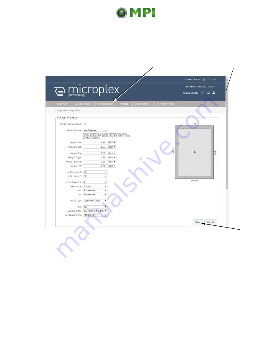
7.3.3.  Page Setup Page 


On the Page Setup page you can for example set the paper size and the margins 
for the printouts.


Fig.


7.3.3.a  logiJET T4-2 /T6-2: Page Setup page of the  MICROPLEX WebPanel  


If the lower part of the menu page is not visible: 
Please use the scroll bar at the right side of the screen to make the lower part of 
the menu page visible.  


Click on „Configuration“ and select the menu item „Page Setup“, to get to the 

Page Setup page, that is shown above. 


(or click on the button „Configuration Page Setup“ on the Overview page of the MICROPLEX 
WebPanel, compare  Fig. 7.2.a) 


Click on the adjustable values, use the input fields.  


Click the Save button to finalize your settings.


Calls up the   
Page Setup page 


Scroll bar 

Mantenimiento Periféricos Informáticos C/Canteras, 15 28860 Paracuellos de Jarama (Madrid) Tel: 00 34 917481604  Web: https://mpi.com.es/

Summary of Contents for logiJET T4-2

Page 1: ...______________________________________________________________________________ logiJET T4 2 logiJET T6 2 with RFID optional Operator s Manual Edition 2 2 Mantenimiento Perif ricos Inform ticos C Cante...

Page 2: ...s assumed for the accuracy of the contents of the documentations MICROPLEX reserves the right to alter technical or other specifications with no prior notice Deviations in the documentations from prev...

Page 3: ...ventions 12 1 6 CE Conformity 13 1 7 General Safety Regulations 14 2 Installation 17 2 1 Printer Unpacking 17 2 2 Check List 19 2 3 Printer Installation 20 2 4 Printer Components 21 3 Media and Ribbon...

Page 4: ...Remotely via Website IP Admin Panel 55 7 1 Abstract 55 7 2 Connecting the Printer to the Network 55 7 3 Remote Control via the integrated Website WebPanel 57 7 3 1 Overview Page 57 7 3 2 Configuration...

Page 5: ...aterial Width Adjustment Paper Width 103 9 7 Configuration of Text Margins 104 9 8 Printing the Status Sheet 105 9 9 Show Info IP Address Firmware Release 107 9 10 Printing the Font List 108 9 11 Hexd...

Page 6: ...n 149 10 2 4 Adjusting the Number of RFID Access Timeout 155 10 2 5 Adjusting the Transmission Speed Bit Rate 156 10 2 6 Reading the Label Identification Number automatically 157 10 3 Data Interface S...

Page 7: ...ansport 190 12 4 Rewinder Dispenser and Cutter Error Messages 191 12 5 Print Repetition after an Error 193 13 Measures for Transport and Shipping Repacking 195 14 Specifications 197 15 Appendix 201 15...

Page 8: ..._________ _______________________________________________________________________________________________ MICROPLEX Operator s Manual logiJET T4 2 T6 2 RFID Edition 2 2 Mantenimiento Perif ricos Infor...

Page 9: ...series are provided with a controller that is also used in SOLID laserprinters So the advantages of the thermal print technology are combined with the flexibility of the laserprinter intelligence The...

Page 10: ...l drive RFID subsystem and printhead Fig 1 2 a Block diagram High Frequency Identification technology RFID The multi protocol RF Write Read module is built in in the printers paper path To use the RFI...

Page 11: ...ized 1 4 Fundamentals of Thermal Printing The thermal print technology enables a quiet and fast print process with a high resolution output The printhead produces the image by heating single elements...

Page 12: ...ion injuries may result the function of the printer could be reduced or objects could be damaged This symbol refers to important hints and suggestions on using the printer Disregarding these hints mig...

Page 13: ...perator s Manual logiJET T4 2 T6 2 RFID Edition 2 2 1 6 CE Conformity The printers logiJET T4 2 and logiJET T6 2 with RFID factory option incorporate an integrated compact reader RF Write Read module...

Page 14: ...installed and used in accordance with the instruction manual may cause harmful interference to radio communications This MICROPLEX product and its consumables are designed and tested according to stri...

Page 15: ...e fastened by screws Do not remove or bridge over any safety device Do not push anything into the ventilation apertures Never carry out installations cleanings or maintenance operations which are not...

Page 16: ...lug in or remove interface connectors when the device is switched off In order to disconnect the printer quickly from the main power in case of emergency please note the following For connected printe...

Page 17: ...ipping box etc of your printer may differ in form and optic from the parts shown in the following figure Fig 2 1 a Printer in the shipping box 2 Take the printer and lift it out the box carefully Get...

Page 18: ...PLEX Operator s Manual logiJET T4 2 T6 2 RFID Edition 2 2 Fig 2 1 b Lifting the printer 3 Remove the foil covering the printer 4 Place the printer onto a suitable base see section 2 3 Please retain th...

Page 19: ...level surface until the definitive location is chosen Please make sure that all items are included and that there are no defects Immediately inform your supplier of any damage Open the cardboard box...

Page 20: ...volatile or combustible materials e g a curtain The printer must be connected to an appropriate AC power source 120V AC 60 Hz North America or 230V 50 Hz Europe United Kingdom e g The power source mu...

Page 21: ...ig 2 4 a Main view of the printer Rear view Ethernet interface Centronics interface USB interface Input power connector Power switch Fig 2 4 b Rear view of the printer Window Check the material foil s...

Page 22: ...__________________________________ MICROPLEX Operator s Manual logiJET T4 2 T6 2 RFID Edition 2 2 Fig 2 4 c Printer opened Lower cover Printhead pressure lever Cover Display and Control panel Label su...

Page 23: ..._______________________________________________ MICROPLEX Operator s Manual logiJET T4 2 T6 2 RFID Edition 2 2 Fig 2 4 d Details printer mechanism Platen roller Dispense sensor Ribbon rewind shaft Rib...

Page 24: ...is very important to run tests for your applications Fig 3 a Labels To use the RFID capabilities of this printer you will need the appropriate RFID media This media includes the label backing and an...

Page 25: ...transfer ribbon removal ribbon loading media loading media material setting label continuous page length paper width setting margin setting see chapter 7 to 9 see chapter 5 see chapter 5 see chapter 5...

Page 26: ...operating the ENTER key two times An output of the current setting values can be generated using the Printing the Status Sheet panel function see section 9 8 After each material changing print media...

Page 27: ...hine in the vicinity of the material transport unit Be careful when operating equipment with opened cover hoods setting up work or service Rotating parts can cause injury and it is possible for hair c...

Page 28: ...he diagram above shows the usual winding directions of material and ribbon Pay attention to the different ribbon roll winding directions described in section 5 3 1 Ribbon Loading The figure above show...

Page 29: ...fed media for tear off respectively for further external processing go on like this The tear off roll fed media is easier to insert if the end is gored before inserting as shown in figure 5 2 1 a when...

Page 30: ...2 Fig 5 2 1 b Opening the printer hood 3 Unlock the label supply guide the small locking lever has to be opened by flipping this lever in the direction shown in figure 5 2 1 c by the yellow arrow The...

Page 31: ...a roll must turn counterclockwise when unwinding Take the Tear off roll fed media and hold it in the corresponding way 6 Slide the media roll onto the label roll bar all the way back to the printer s...

Page 32: ...de in too far or you will damage the edge of the label stock Fig 5 2 1 g Setting the label supply guide to the right position 10 Lock the label supply guide the small locking lever has to be closed by...

Page 33: ...outermost position Compare figure 5 2 1 j 13 Feed the label through under the label tension plate under the moveable sensor to the tear off bar Fig 5 2 1 i Inserting the media 14 Align the media to en...

Page 34: ...on 2 2 16 Use the setting knob to adjust the sensor position light barrier If you turn the setting knob clockwise the sensor will move rightward Fig 5 2 1 k Adjusting the sensor position 17 The right...

Page 35: ...nt using the thermal transfer process you still need to insert ribbon Fig 5 2 1 m Closing the pressure lever Pay attention to the following safety instructions Safety instructions The cutter optional...

Page 36: ...he hood of the printer 3 Release the printhead pressure lever to remove the media see section 5 1 Winding Diagram and at the same time pull away the material to the rear 4 Rotate the tear off roll fed...

Page 37: ...e a printer ribbon being wider than the media to print on In the case of printing on abrasive media printhead damaging can be avoided this way To set the ribbon go on like this 1 Switch the printer to...

Page 38: ...3 1 b Different ribbon roll winding directions 6 Slide the ribbon roll onto the ribbon supply shaft all the way back to the printer s inner wall Fig 5 3 1 c Inserting the ribbon roll and the empty rib...

Page 39: ...ead Ribbon Fig 5 3 1 d Feeding through the ribbon below the printhead 9 Route the ribbon to the rewinding mandrel and fasten it to the ribbon sleeve turn up the ribbon once so that the adhesive part a...

Page 40: ...sary tauten the ribbon by turning the rewind shaft 11 Swivel the printhead pressure lever clockwise back to its original position making sure it clicks into place Fig 5 3 1 f Locking the pressure leve...

Page 41: ...s in ribbon material ribbon wrinkles may occur during printing To solve this problem the ribbon tension has to be increased 1 Push the adjusting ring of the ribbon rewind shaft towards the ribbon roll...

Page 42: ...shaft clockwise to increase the ribbon tension while you hold the ribbon roll with the other hand Fig 5 3 2 a Adjusting the ribbon tension at the ribbon supply shaft 5 Check that the ribbon has no fo...

Page 43: ...nd shaft towards the ribbon roll See figure 5 3 2 a 2 Then turn the adjusting ring of the ribbon rewind shaft counterclockwise to decrease the ribbon tension while you hold the ribbon roll with the ot...

Page 44: ...used up ribbon has to be removed the steps 5 and 6 have to be omitted 1 Switch the printer to OFF LINE mode 2 Open the the printer hood 3 Release the printhead pressure lever 4 The core of a used up...

Page 45: ...for the next thermal transfer operation if necessary protect the ribbon against unintentional unwinding The ribbon has to be loaded as described in section 5 3 1 7 Rotate the rewind shaft until the f...

Page 46: ...he position of the spring boxes and the contact pressure are both adjustable The spring boxes are located above the printhead Spring boxes Fig 5 4 a Printhead contact pressure position of the spring b...

Page 47: ...ressure lever Fig 5 4 b Swivel the printhead pressure lever upward counterclockwise 3 Please adjust the lateral positions of the thermal printhead spring boxes in accordance to the current material wi...

Page 48: ...ting screw for the printhead pressure Printhead pressure lever Fig 5 4 d Detailed picture of a spring box 4 Swivel the printhead pressure lever clockwise back to its original position making sure it c...

Page 49: ...spring box is provided with a setting screw to enable printhead pressure adjustment Be careful when using a flat blade screwdriver to avoid damaging the printer Turning the screw clockwise increases...

Page 50: ..._________________ _______________________________________________________________________________________________ MICROPLEX Operator s Manual logiJET T4 2 T6 2 RFID Edition 2 2 Mantenimiento Perif ric...

Page 51: ...y 1 Make sure the printer computer and any other attached devices are turned off and unplugged 2 Use a proper interface line to connect the printer to the computer or to attach the printer to the netw...

Page 52: ...rounded outlet 2 Turn on the printer The power switch is located at the rear side of the printer see section 2 4 Printer Components As soon as the printer s warm up phase is finished the printer goes...

Page 53: ...e display messages the Light ring of the ONLINE key indicates the printer status The printer is ready ON LINE to receive data from the host The printer is not ready to receive data from the host OFF L...

Page 54: ...his key is used to start the cutter the cutter is available as an option In the OFF LINE mode the paper is conveyed one format length further FEED after using this key These keys are used for working...

Page 55: ...tory default settings IP Address 192 168 128 128 Subnet mask 255 255 255 0 Gateway 0 0 0 0 2 The status sheet see section 9 8 contains information about the current printer configuration and the IP ad...

Page 56: ...ogiJET T4 2 T6 2 Overview page of the MICROPLEX WebPanel On the Overview page the printer status is displayed as well as information on the controller and firmware version of your device Hint More det...

Page 57: ...ontrol via the integrated Website WebPanel The print system settings can only be changed if the printer is turned OFF LINE 7 3 1 Overview Page On the Overview page the printer status is displayed as w...

Page 58: ...printer status sheet view it and save it to a file To change a parameter click on this specific parameter Select for example the input field Inventar Information and then enter a new inventory number...

Page 59: ...ract Please click on the parameter you wish to change Click on the online status message to turn the printer offline Clicking on the offline message turns the printer online again Click on Configurati...

Page 60: ...page of the MICROPLEX WebPanel If the lower part of the menu page is not visible Please use the scroll bar at the right side of the screen to make the lower part of the menu page visible Click on Conf...

Page 61: ...al logiJET T4 2 T6 2 RFID Edition 2 2 7 3 4 Network Page On the Network page you can configure the parameters for a network connection of the printer Fig 7 3 4 a logiJET T4 2 T6 2 Network page of the...

Page 62: ...Edition 2 2 Click on the input field for the IPAddress and then enter a new IPAddress Hint The best way is to write the new IPAddress for example on a label and put it onto the device Click on the in...

Page 63: ...age in the event of a fault Or you are on the Overview page of the MICROPLEX WebPanel then you can click on the button Device Status compare Fig 7 2 a Fig 7 3 5 a logiJET T4 2 T6 2 Device Status page...

Page 64: ...ge If you use wrong parameters the printer could hang up Before you change EEPROM parameters of the print system it is recommended to generate a Status Sheet This facilitates a reset of the printer re...

Page 65: ...___________________________________ MICROPLEX Operator s Manual logiJET T4 2 T6 2 RFID Edition 2 2 The fourth line Word 49 to Word 64 cannot be changed by the user Hint For more details refer to our o...

Page 66: ...s Manual logiJET T4 2 T6 2 RFID Edition 2 2 7 3 7 User Control Page On the User Control page you can register all users with user name and password Fig 7 3 7 a logiJET T4 2 T6 2 User Control page of t...

Page 67: ...IP Panel enables you to do the well known operating steps 1 Type the IP address of the printer in the address bar of your Web browser compare the previous sections example http 192 168 128 128 The br...

Page 68: ...f the printer of the logiJET T4 2 T6 2 pops up Fig 7 4 1 b The MICROPLEX IP Admin Panel is the virtual control panel of the logiJET T4 2 T6 2 This virtual control panel enables you to get access to th...

Page 69: ...____________________________ MICROPLEX Operator s Manual logiJET T4 2 T6 2 RFID Edition 2 2 7 4 2 Details of the IP Panel Elements Fig 7 4 2 a MICROPLEX IP Panel virtual control panel of the logiJET T...

Page 70: ...D Edition 2 2 Buttons Panel keys The key turns the printer ON OFF LINE These keys are used for working within the different levels of the menu structure This structure and the panel functions are desc...

Page 71: ...printer configuration are effective only as long as the printer stays turned on To select such changes temporarily the user must terminate the change of function by pressing the ENTER key one single...

Page 72: ...was turned on and as soon as the warm up phase is finished the printer goes into the ON LINE Mode Printer messages are displayed on the control panel display This symbol shows the ONLINE key The print...

Page 73: ...ine Spacing ON LINE mode OFF LINE mode in inch Measure length Print Direction Continuous Label withGap Sync Sens Level Two Up Mode RFM Key lock Extended Menu Image Y Pos Process TearOff Mode Service M...

Page 74: ...ONLINE key The printer is turned OFF LINE with this key With this key ENTER key you get into the first menu level of the menu structure The NEXT key and the PREVIOUS key are used to move within the m...

Page 75: ...igit digit 1 of the function value is still arrived the currently displayed function value is stored In case of a multi digit function value the value of the currently chosen digit will be changed via...

Page 76: ...de A Return to the ON LINE mode step by step Pressing the ONLINE key takes the user to the respective previous menu level Aim is to jump back to Menu Level 1 The next ONLINE key pressing switches the...

Page 77: ...certain function First the elements of the diagram are explained The sequence on the left describes which keys have to be pressed briefly in succession In this example the ONLINE key has to be presse...

Page 78: ...__________________________ _______________________________________________________________________________________________ MICROPLEX Operator s Manual logiJET T4 2 T6 2 RFID Edition 2 2 Mantenimiento...

Page 79: ...This function serves to show some basic information about your printer the IP Address Firmware Release Serial Number and the current Printer Emulation Printing the Menu Page see section 9 14 This fun...

Page 80: ...evice operates without ribbon direct thermal media is required While thermal transfer printing a ribbon is needed to transfer the print contents onto the media see chapter 5 Handling of Consumables to...

Page 81: ...nu structure Press the NEXT or PREVIOUS key until Engine is displayed The menu item Engine is selected Press the NEXT or PREVIOUS key until Process is displayed The menu item Process is selected Press...

Page 82: ...ith transparent or register gaps The Reflex Sensor Reflex Photoelectric Switch is suitable for materials with markings Black Marks Panel display ON LINE OFF LINE Menu Level 1 Paper Menu Paper Size Pap...

Page 83: ...EX Operator s Manual logiJET T4 2 T6 2 RFID Edition 2 2 Save as Setup The printer is adjusted to material with Black Marks In addition this new value can be saved as setup value using the ENTER key Af...

Page 84: ...to enable controlling of consumable movements Synchronization The upper media sensor Transparent sensor as well as the lower media sensor Reflex sensor are located below the printhead mounting Move t...

Page 85: ...guide to its outermost position Compare figure 9 3 1 c 4 Insert the consumables refer to section 5 for details Fig 9 3 1 b Inserting the media 5 Slide the material guide inwards until it contacts the...

Page 86: ...2 2 7 Use the setting knob to adjust the sensor position light barrier If you turn the setting knob clockwise the sensor will move rightward Fig 9 3 1 d Adjusting the sensor position 8 The right posi...

Page 87: ...Directly over the hole Notched tag Lower and upper sensors Gap Directly over the notch 10 Set the lower sensors to the lateral position of the gaps or marks of your material Compare the yellow arrows...

Page 88: ...or rea Please follow the instructions Message Load Backing Message Load Black Mark Message Remove Paper Close the printhead and confirm with ENTER key Open the printhead Message Load Paper is displaye...

Page 89: ...menu structure Press the NEXT or PREVIOUS key until Engine is displayed Press the ENTER key this selects the Engine menu Press the NEXT or PREVIOUS key until Sync Menu is displayed Press the ENTER ke...

Page 90: ...the system The panel functions Sensor Test and Sync Sens Level serve to adjust the Sync sensors Reflex sensor and Gap sensor to special media material to print on The following sections describe the s...

Page 91: ...to carry out this operations Please be especially careful when carrying out the following operations to avoid maladjustments and damaging the printer Start the printer in the Service Mode Turn the pr...

Page 92: ...ack mark of your material in the sensor area Set the switching threshold of the Reflex sensor Set the switching threshold to the middle between the paper level and the black mark level Save the new sw...

Page 93: ...CV value Load paper into the sensor The sensor measured value VV level of the paper not black mark should count less than 10 If the VV level is too high increase CV sensor current Put a black mark in...

Page 94: ...TER once again Measure both sensor levels once again thereby notice the values for liner and label You need the two level values of your material for the following switching threshold adjustment Save...

Page 95: ...ference value for sensor current CV is modifiable and has an effect on the VV value Gap Use the NEXT and PREV keys to set the CV value Approx CV value Put the liner not the label of your material into...

Page 96: ...ues in have to be measured Place every specific zone of the material in the photoelectric sensor area and read the level values Example Self adhesive material with black bars across the label Zone of...

Page 97: ...ress the ENTER key this selects the Engine menu Press the NEXT or PREVIOUS key until Sync Menu is displayed Press the ENTER key this selects the Sync Menu Press the NEXT or PREVIOUS key until Sync Sen...

Page 98: ..._____ MICROPLEX Operator s Manual logiJET T4 2 T6 2 RFID Edition 2 2 Nach dem Abschluss der Einstellung der Sensoren ist der Drucker jetzt erst einmal auszuschalten Dies ist erforderlich um den Servic...

Page 99: ...offset is approximately 20 mm Please execute this offset adjusting after you have successfully adjusted the Sync sensors See previous sections Panel display ON LINE OFF LINE Menu Level 1 Engine Print...

Page 100: ...position is shifted 1 mm against the feed direction In addition this new value can be saved as setup value using the ENTER key After this decision turn the printer ON LINE again Press the ON LINE key...

Page 101: ...E with this key The ENTER key gives the user access to the menu structure Press the NEXT or PREVIOUS key until Paper Menu is displayed Press the ENTER key to select the paper menu Press the ENTER key...

Page 102: ...n 9 5 2 Configuration of Semiautomatic Label Length Measurement The panel function logiJET T4 2 Paper Menu Paper Size Page Length Auto Measurement serves to switch the semiautomatic label length measu...

Page 103: ...is displayed Press the ENTER key to select the paper menu Press the ENTER key to select the paper size menu Press the NEXT or PREVIOUS key until Paper Width is displayed Press the ENTER key to adjust...

Page 104: ...NTER key gives the user access to the menu structure Press the NEXT or PREVIOUS key until Page Menu is displayed Press the NEXT or PREVIOUS key until Margin is displayed Press the NEXT or PREVIOUS key...

Page 105: ...t contains information about the current printer configuration and the available fonts Panel display ON LINE OFF LINE Menu Level 1 Status Sheet Status Sheet Notes Turn the printer OFF LINE with this k...

Page 106: ...uration parameters Printed in plain text Controller version memory serial number Firmware release Interface parameters of Parallel Serial USB Network Ethernet Printer emulation User RAM free User RAM...

Page 107: ...Notes Turn the printer OFF LINE with this key The ENTER key gives the user access to the menu structure Press this key Menu Level 1 is selected Press the NEXT or PREVIOUS key until Show Info is displa...

Page 108: ...the concerning PCL selection commands These commands contain information on font width and font height see section 9 22 Font Selection too Panel display ON LINE OFF LINE Menu Level 1 Status Sheet Fon...

Page 109: ...Panel display ON LINE OFF LINE Menu Level 1 Status Sheet Hexdump Hexdump Notes Turn the printer OFF LINE with this key The ENTER key gives the user access to the menu structure Menu level 1 is select...

Page 110: ...LINE Menu Level 1 Status Sheet Normal Print FF Normal Print FF Notes Turn the printer OFF LINE with this key The ENTER key gives the user access to the menu structure Press the NEXT or PREVIOUS key un...

Page 111: ...n e g paper jam The data contained in the input buffer before the interruption are cleared Panel display ON LINE OFF LINE Menu Level 1 Status Sheet Cancel Job Cancel Job Notes Turn the printer OFF LIN...

Page 112: ...nu page please use a large paper Panel display ON LINE OFF LINE Menu Level 1 Status Sheet Menu Page Menu Page Notes Turn the printer OFF LINE with this key The ENTER key gives the user access to the m...

Page 113: ...s facilitate error analysis Panel display ON LINE OFF LINE Menu Level 1 Status Sheet Sliding Pattern Sliding Pattern Notes Turn the printer OFF LINE with this key The ENTER key gives the user access t...

Page 114: ...on is displayed The currently set value for he timeout is displayed here 30 seconds Pressing the UP or DOWN key changes the value of the current digit Digit3 left position in this example 0 Pressing t...

Page 115: ...Save as Setup Notes Turn the printer OFF LINE with this key The ENTER key gives the user access to the menu structure Press the NEXT or PREVIOUS key until Configuration is displayed Press the NEXT or...

Page 116: ...EPL2 ZPL II Zebra Programming Language CUPS Raster Optional HP PCL5 factory option only Kyocera Prescribe Printronix IGP PGL LabelPoint TIFF CCITT group 4 Postscript IPDS via PPD PPR Protocol TEC B6x...

Page 117: ...ace Language German English Save as Setup Notes Turn the printer OFF LINE with this key The ENTER key gives the user access to the menu structure Press the NEXT or PREVIOUS key until Configuration is...

Page 118: ...Digit1 2626 Save as Setup Notes Turn the printer OFF LINE with this key The ENTER key gives the user access to the menu structure Press the NEXT or PREVIOUS key until Configuration is displayed Press...

Page 119: ...kB Save as Setup Notes Turn the printer OFF LINE with this key The ENTER key gives the user access to the menu structure Press the NEXT or PREVIOUS key until Configuration is displayed Press the NEXT...

Page 120: ...nu Level 1 Configuration Interface Factory Default Save as Setup Notes Turn the printer OFF LINE with this key The ENTER key gives the user access to the menu structure Press the NEXT or PREVIOUS key...

Page 121: ...Font Number Font 600 Font 5507 Save as Setup Notes Turn the printer OFF LINE with this key The ENTER key gives the user access to the menu structure Press the NEXT or PREVIOUS key until Page Menu is...

Page 122: ...c 4508 P 8 1 Helgoland 4510 P 10 Helgoland 4714 P 14 4 Helgoland Bold 5507 20 7 Langeoog 5508 16 6 7 9 Langeoog 5509 15 9 1 Langeoog 6610 10 10 1 Juist Monosp 9210 P 10 1 Tasmanien 9310 P 10 1 Tasmani...

Page 123: ...Neuwerk Italic 9500 P SC Neuwerk Bold Italic 9600 P SC Neuwerk Bold 0060 SC Plakatschrift 9501 P SC Neuwerk II Condensed Italic 9601 P SC Neuwerk II Condensed Bold Ital 9801 P SC Neuwerk II Condensed...

Page 124: ...user access to the menu structure Press the NEXT or PREVIOUS key until Page Menu is displayed Press the NEXT or PREVIOUS key until Orientation is displayed Press the NEXT or PREVIOUS key until the de...

Page 125: ...Save as Setup Notes Turn the printer OFF LINE with this key The ENTER key gives the user access to the menu structure Press the NEXT or PREVIOUS key until Page Menu is displayed Press the NEXT or PRE...

Page 126: ...anel display ON LINE OFF LINE Menu level 1 Engine Printspeed 6 inch s 4 inch s Save as Setup Notes Turn the printer OFF LINE with this key The ENTER key gives the user access to the menu structure Pre...

Page 127: ...key gives the user access to the menu structure Press the NEXT or PREVIOUS key until Engine is displayed Press the NEXT or PREVIOUS key until Contrast is displayed The currently set value is displayed...

Page 128: ...NTER key gives the user access to the menu structure Press the NEXT or PREVIOUS key until Engine is displayed Press the NEXT or PREVIOUS key until Image X Pos is displayed The panel function Image Shi...

Page 129: ...2 RFID Edition 2 2 Example for shifting the image to the X direction Feed direction print direction Printout after the image shifting to the X direction In this example the value of the Image X Positi...

Page 130: ...ives the user access to the menu structure Press the NEXT or PREVIOUS key until Engine is displayed Press the NEXT or PREVIOUS key until Image Y Pos is displayed The panel function Image Shifting to t...

Page 131: ...2 RFID Edition 2 2 Example for shifting the image to the Y direction Feed direction print direction Printout after the image shifting to the Y direction In this example the value of the Image Y Positi...

Page 132: ...d to adjust the printer configuration Start the printer in the Service Mode Turn the printer on Panel display Service Mode Notes Before starting the printer the left panel key and the panel key in the...

Page 133: ...ter OFF LINE with this key The ENTER key gives the user access to the menu structure Press the NEXT or PREVIOUS key until Engine is displayed Press the NEXT or PREVIOUS key until Service Mode is displ...

Page 134: ...ne Printspeed TearOff Menu TearOff Mode OFF ON Save as Setup Notes Turn the printer OFF LINE with this key The ENTER key gives the user access to the menu structure Press the NEXT or PREVIOUS key unti...

Page 135: ...isjoin the material along at the perforation The tear off mode is not carried out if the next page is already ready to print In this case the next page is printed instead A draw back of the material c...

Page 136: ...ormal 1 1 Mode Save as Setup Notes Turn the printer OFF LINE with this key The ENTER key gives the user access to the menu structure Press the NEXT or PREVIOUS key until Engine is displayed Press the...

Page 137: ...volume in relation to a certain time Tear off edge 1 Print 2 Print end 3 Feed then cut 4 Return Antenna Print head Tag Position example Label printed Label unprinted Hints In the RFID mode a tear off...

Page 138: ...f edge or cutter Tear off edge or cutter Non printable area 1 Print 2 Feed 3 Cut Druckkopf Label unprinted Antenna Print head Tag Position example Label printed Hints In the RFID mode a tear off singl...

Page 139: ...ition 2 0 mm Position 2 5 mm Save as Setup Notes Turn the printer OFF LINE with this key The ENTER key gives the user access to the menu structure Press the NEXT or PREVIOUS key until Engine is displa...

Page 140: ...ed then cut Printhead Setting range for the cutting position Offset from 0 to 4 2mm Page printed Please note Avoid to set the cutting offset to or near zero because the media may drop out of the trans...

Page 141: ...ey gives the user access to the menu structure Press the NEXT or PREVIOUS key until Network is displayed Press the ENTER key to select the Network menu Press the NEXT or PREVIOUS key until IP Assign i...

Page 142: ...assigned select the item DHCP from the network submenu IP Assign The parameters Subnet Mask and Gateway are configured in the same way as described above Please select the concerning panel functions f...

Page 143: ...utonegotiation is the recommended setting If you set the Duplex Speed parameters manually you may experience problems Wrong settings can slow down the speed of the link worst case communication does n...

Page 144: ...______________ _______________________________________________________________________________________________ MICROPLEX Operator s Manual logiJET T4 2 T6 2 RFID Edition 2 2 Mantenimiento Perif ricos...

Page 145: ...for printers incorporating the integrated compact reader factory option 10 1 Integrated RF Write Read module A Block diagram of High Frequency Identification technology RFID Radio Frequency IDentifica...

Page 146: ...__________________ _______________________________________________________________________________________________ MICROPLEX Operator s Manual logiJET T4 2 T6 2 RFID Edition 2 2 Mantenimiento Perif ri...

Page 147: ...etup Notes Turn the printer OFF LINE with this key The ENTER key gives the user access to the menu structure Press the NEXT or PREVIOUS key until Engine is displayed Press the NEXT or PREVIOUS key unt...

Page 148: ...col Gen 2 ISO18000 6b Saved Notes Turn the printer OFF LINE with this key The ENTER key gives the user access to the menu structure Press the NEXT or PREVIOUS key until Engine is displayed Press the E...

Page 149: ...INE Menu Level 1 Engine Printspeed RFID Menu RFID Mode Search Tag Pos Searching Tag Position 20 mm Notes Turn the printer OFF LINE with this key The ENTER key gives the user access to the menu structu...

Page 150: ...emedies No Tag Found The RFID tag was not found in the RF Field area inside the printer where RFID tag is read check supply loading rerun the automatic transponder position measurement further remedie...

Page 151: ...ag position values and ascertain the RFID reading results for each position The setting range for the Tag position is 0 up to 254 mm 1 Take a peace of your label material and use a ruler to measure th...

Page 152: ...Position 48 mm Save as Setup Notes Turn the printer OFF LINE with this key The ENTER key gives the user access to the menu structure Press the NEXT or PREVIOUS key until Engine is displayed Press the...

Page 153: ...the printer antenna 5 Please ascertain how far the label material has to be moved until it would be positioned in the optimal position right above the center of the printer antenna Compare the figure...

Page 154: ...inter constantly If for example at the positions 50mm and 54mm the message Read Time Out or Multi Tag Read is displayed shortly this positions are not interesting Using this RFID inlay the best readin...

Page 155: ...8 Save as Setup Notes Turn the printer OFF LINE with this key The ENTER key gives the user access to the menu structure Press the NEXT or PREVIOUS key until Engine is displayed Press the NEXT or PREVI...

Page 156: ...D Menu RFID Mode Bit Rate T 40 R 160 kBit T 40 R 40 kBit Saved Notes Turn the printer OFF LINE with this key The ENTER key gives the user access to the menu structure Press the NEXT or PREVIOUS key un...

Page 157: ...automatically and showing the reading results on the panel display Panel display ON LINE OFF LINE Menu Level 1 Engine Printspeed RFID Menu RFID Mode Autom Read ID OFF ON Save as Setup Notes Turn the...

Page 158: ...ta from the printer via the active interface or via a separate status channel which is independent of the data channel Physically the status channel may be the serial interface or the Ethernet interfa...

Page 159: ...r of RFID labels for example and to transmit it to the host via the printer s status channel The user may add personalized ID data a page identification number e g to send it to the host too This allo...

Page 160: ...l that is below the RF Write Read module of the printer Please refer to the example in figure 10 4 1 a This command can be used to teminate RFID processing of label B in order to cut label A immediate...

Page 161: ...eading position if the function Reading the Label Identification Number automatically is selected see section 8 2 6 Antenna of the Write Read module Print head Tag Position example Label A printed Lab...

Page 162: ...rinting Send the following command to the printer via the print data channel rf 01 This command leads to a status message sent by the printer The status message includes the Label ID Number 1020 S Lab...

Page 163: ...e Data are given as a text string the data format can be set by the parameter k12 binary default see section 10 4 1 The length of the data is flexible Therefore the end of data has to be marked by a s...

Page 164: ...s ddd string length 3 digits decimal 000 is to be used if no text string shall be added The maximum string length is 31 characters Page ID Text string ASCII characters A page identification number e g...

Page 165: ...el the RFID status request command looks as follows 0019 009 PAGE 0001 The command described above is send to the printer together with the print data for this label This command leads to a ready mess...

Page 166: ...o 4 6 digit decimal status number ASCII character S Separator SPACE e g Page ID Text string for example page identification number As supplied in the status request command compare section 10 4 4 If n...

Page 167: ...s is a answer to a RFID support command Label ID 058000098B7C1F6B Identification number of the label in this example the string includes 16 characters b Generating a Page ID Number Receiving the RFID...

Page 168: ...er Identification Number If the printer can not read and send the transponder identification number of the label Label ID the printer marks the print image as an error label two black bars are printed...

Page 169: ...as not found in the RF Field area inside the printer where RFID tag is read or the RFID tag was found in the RF Field but could not be read check supply loading if you made supply or print position se...

Page 170: ...nd read program etc has failed to complete in the maximum amount of allowed time increase the number of retries See section 10 2 4 Adjusting the Number of RFID Access make sure the media has been load...

Page 171: ...there is a paper jam compare section 12 3 Incorrect Media Transport remove the jammed consumables completely reload the consumables compare section 5 2 if you made supply or print position settings m...

Page 172: ...ter Panel display Explanations Remedies RFID Error Device Time Out The integrated RF write read module option is not connected or defective make sure the RF write read module is installed correctly ch...

Page 173: ...a regular and conscientious performance of the following operations the printer is guaranteed to always work at an optimum reliability For safety pull out the mains plug first Make sure the elements...

Page 174: ...perations please load the wanted consumables again see chapter 5 Handling of Consumables 11 1 1 Printer Cabinet Cleaning Soilings like dust grease or similar things can be removed with a soft lint fre...

Page 175: ...e is no need to disassemble or remove the printhead The printhead can be damaged by electrostatic charges Therefore first of all touch a properly grounded part of the printer the base plate of the pri...

Page 176: ...b rough side uppermost Fig 11 1 2 b Cleaning the printhead using a cleaning strip Close the printhead pressure lever and then move the cleaning strip in and against the paperfeed direction see figure...

Page 177: ...t smoke Use a soft lint free cloth moisten it with spirit and then use it to wipe several times along the print area of the printhead compare figure 11 1 2 a Allow the printhead to dry for 2 3 minute...

Page 178: ...ers can be soiled by the print media e g with adhesive residues For the following cleaning operations the hints of section 11 1 2 are valid too Stickings can be removed best with a soft lint free clot...

Page 179: ...ure wearing of the printhead Only a MICROPLEX trained operator is allowed to exchange the printhead The following operations have to be done to carry out the printhead exchange Printhead removal and i...

Page 180: ...ut and swivel it upward counterclockwise 4 Remove the ribbon see section 5 3 3 5 Remove the printmedia see section 5 2 2 Please pay attention to the following Wait at least 3 minutes after switching o...

Page 181: ...on 2 2 Fig 11 2 1 b Gently pull the printheada little bit towards you Tip Have a look at the printhead s position in the side guides of the printer Later on the new printhead has to be assembled just...

Page 182: ...D Edition 2 2 8 Take the new printhead 9 Gently insert the new printhead assembly into the side guides of the printer In the same way the old printhead was positioned there Fig 11 2 1 d Insert the pri...

Page 183: ..._______________________________________________ MICROPLEX Operator s Manual logiJET T4 2 T6 2 RFID Edition 2 2 11 Gently press the printhead into its carriage until it clicks into place Fig 11 2 1 f I...

Page 184: ...e printmedia Fig 11 3 a Principle view of the print process While printing small labels the printhead may come in contact with the print roller just in that area that isn t covered by the label This m...

Page 185: ...peration The ring around the ENTER key is no longer illuminated then Please address the problems described in this chapter yourself especially the consumable replacement Please regard the following su...

Page 186: ...to its original position making sure it clicks into place Fig 12 1 a Locking the pressure lever Paper End insert a media roll fed media e g make sure the media has been loaded correctly compare secti...

Page 187: ...he avoiding of paper jams please take notice of section 12 3 Incorrect Media Transport HeadNot Found the printhead is not connected or faulty Head defective or Print Head Err the printhead is defectiv...

Page 188: ...justing the Right Pressure Value check the ribbon transport load the ribbon again if necessary see section 5 3 increase the contrast see section 9 26 choose different consumables adjust media to the r...

Page 189: ...printhead see section 11 1 2 check the ribbon transport load the ribbon again if necessary see section 5 3 also see section 12 3 Incorrect Media Transport the printhead has to be exchanged if for exa...

Page 190: ...bbon has been loaded correctly compare section 5 3 clean the transport rollers see section 11 1 3 No straight transport of the consumables torsion or folding of the ribbon e g check if the ribbon has...

Page 191: ...nd NotFound The optional rewinder is selected but not connected or defective make sure the rewinder is installed correctly Compare section 9 29 Peripheral Device Activation Unselect the rewinder if th...

Page 192: ...9 Dispenser Error An error occured during dispenser operation check for a paper jam Remove the jammed paper reload the consumables paper CutterNotFound The optional cutter is selected but not connecte...

Page 193: ...an error occurs all the pages on the paper path will be printed again This ensures that no data will get lost The exact number of pages to repeat depends on the format length and the position where t...

Page 194: ..._____________ _______________________________________________________________________________________________ MICROPLEX Operator s Manual logiJET T4 2 T6 2 RFID Edition 2 2 Mantenimiento Perif ricos I...

Page 195: ...amaging during transportation The following list gives you an overview of the working steps necessary for repacking Pay attention to the notices located on the products and the hints given in the Serv...

Page 196: ..._______________________ _______________________________________________________________________________________________ MICROPLEX Operator s Manual logiJET T4 2 T6 2 RFID Edition 2 2 Mantenimiento Per...

Page 197: ...dots per inch horizontal and vertical logiJET T4 2 logiJET T6 2 up to 120 mm up to 174 mm 105 mm 168 mm 0 06 up to 0 25 mm parallel IEEE 1284 Centronics MP BUS GPIO Interface SPS Control optional seri...

Page 198: ...g and reading The technical specifications of this compact reader module are listed below The reader is fully compliant to the European telecommunication regulation ETSI EN 300 220 869 525 MHz RFID Re...

Page 199: ...out the usage of tools Consumables can be different depending on the printer type The most important consumable for example is toner Usually the utilization time of these materials is given as a numbe...

Page 200: ...of a component but also on a possible loss of print quality in the printouts MNPSQ Mean Number of Prints with Specified Quality SQ This value is often associated with Lifetime This term is not correc...

Page 201: ...or this status channel the serial interface USB of the printer is used for example Two modes are available In the first one some messages will be sent automatically within the second mode you may ask...

Page 202: ...you want to change one bit of a word you have to program the complete word It is not possible to change one bit only Example Word FFFF Bit No 16 15 14 13 12 11 10 9 8 7 6 5 4 3 2 1 Binary 1 1 1 1 1 1...

Page 203: ...the EEPROM sequence EEPROM word 30 Bit 1 8 Separator Bit 9 16 Terminator Please use the IDOL command ESC ESC ee for setting the word 30 Example Set the following configuration for the separator and te...

Page 204: ...ll be warmed up and ready for printing All settings will be switched to the EEPROM values 1011 IDLE state This is not an automatical message This message will be sent only after a request ESC ESC 0011...

Page 205: ...No error printer ON LINE 2035 Toner low 2037 Paper jam 2039 No paper 2040 Cover open 2042 Service call 3001 Paper near out one feeder empty at auto cass mode This message will appear in the auto cass...

Page 206: ...__________ _______________________________________________________________________________________________ MICROPLEX Operator s Manual logiJET T4 2 T6 2 RFID Edition 2 2 Mantenimiento Perif ricos Info...

Page 207: ...ts 3 continuous 82 contrast 127 control panel 51 control panel elements 53 conventions 12 costs per page 199 cut key 54 cutter 54 191 cutter activation 132 cutting menu 135 cutting mode 134 135 cuttin...

Page 208: ...2 label ID 166 label length 102 labels 10 language 117 LCD Display 53 LED 53 light sensor position 84 light sensor type 82 M margin 104 material 9 82 material width 103 measures transport 195 media 9...

Page 209: ...process 80 print quality 24 188 200 print repeat 193 print speed 9 126 197 print width 103 printer components 21 printer installation 20 printer status 201 printer status messages 205 printhead cleani...

Page 210: ...ode 125 symbols 12 Sync sensor level 88 90 synchronization 84 syntax of diagrams 77 T tag position 149 tear off edge activation 132 tear off media 29 tear off mode 134 137 161 tear off position 99 139...

Page 211: ...________ _______________________________________________________________________________________________ MICROPLEX Operator s Manual logiJET T4 2 T6 2 RFID Edition 2 2 Mantenimiento Perif ricos Inform...

Reviews: