background image

Open

DVVA II 4000

5-2                                                    

400-42803-01 (Rev B) - July 2017

Open

Open

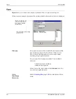
 allows you to create a new sample or parameter file, or to open an existing one. 

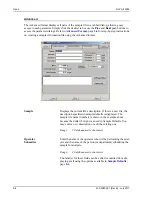
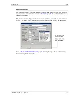
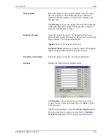
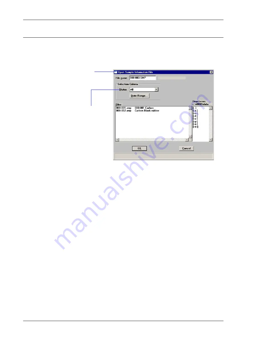
When you open a sample or parameter file, a dialog similar to the one shown below is displayed. 

File name

For 

sample information

 files: contains the next sequenced file 

name (number) generated by the software. If this is a new 
file, you can accept this number or you can enter a name 
consisting of up to eight characters.

For 

parameter files

: displays an asterisk (*) and a default 

extension:

*.ANC for analysis conditions
*.RPO for report options

If this is a new file, enter a name in the 

File name 

field. You 

can enter up to eight characters. 

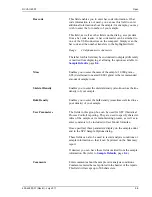
Status

Date Range

Directories

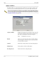
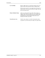
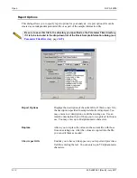
Refer to 

Selecting Files

, page 

2-10

 for a description of these 

fields.

Title bar indicates the type 
of file you are opening; in 
this example, a Sample 
Information file.

Does not display when opening 
parameter files.

Summary of Contents for DVVA II 4000

Page 1: ...DVVA II 4000 Dynamic Void Volume Analyzer Operator s Manual Rev B 400 42803 01 July 2017 ...

Page 2: ...ration Micromeritics is a registered trademark of Micromeritics Instrument Corporation Windows is a registered trademark of Microsoft Corporation Micromeritics Instrument Corporation 2013 2017 All rights reserved Printed in the U S A The software described in this manual is furnished under a license agreement and may be used or copied only in accordance with the terms of the agreement ...

Page 3: ... the following conditions 1 Certain products sold by MICROMERITICS are the products of reputable manufacturers sold under their respective brand names or trade names We therefore make no express or implied warranty as to such products We shall use our best efforts to obtain from the manufacturer in accordance with his customary practice the repair or replacement of such of his products that may pr...

Page 4: ......

Page 5: ...e 2 6 Shortcut Menus 2 6 Shortcut Keys 2 6 Dialog Boxes and Subdialog Boxes 2 8 Selecting Files 2 10 Selecting Reports 2 12 File Name Conventions 2 13 Menu Structure 2 14 Windows Menu 2 15 Help Menu 2 15 3 OPERATIONAL PROCEDURES Specifying Sample File Defaults 3 1 Advanced Format 3 1 Basic Format 3 4 Creating Sample Information Files 3 6 Advanced Format 3 6 Basic and Restricted Formats 3 8 Creatin...

Page 6: ... Reinstalling Calibration Files 4 18 Uninstalling the Analysis Program 4 19 5 FILE MENU Description 5 1 Open 5 2 Sample Information 5 3 Advanced 5 4 Basic 5 7 Restricted Format 5 9 Analysis Conditions 5 10 Report Options 5 12 Summary Report 5 15 Standard Table 5 18 Pressure Table Report 5 19 Trend Plots 5 20 Uncorrected Data Report 5 21 Sample Log Report 5 21 Compression Reports 5 22 Modified Heck...

Page 7: ... Piston Home 6 17 Upper Zero Force 6 18 Zero Height 6 18 Lower Force Scale 6 18 Normalization 6 19 7 REPORTS MENU Description 7 1 Start Report 7 2 Close Reports 7 4 Open Report 7 4 SPC Report Options 7 5 Regression Report 7 6 Control Chart 7 9 Printed Reports 7 13 Header 7 13 Onscreen Reports 7 14 Tool Bar 7 15 Shortcut Menus 7 18 Tabular Reports 7 18 Graphs 7 19 Zoom Feature 7 22 Axis Cross Hair ...

Page 8: ...ion 2 9 7 Action 3 9 7 Action 4 9 7 Lower Piston Release Procedure 9 8 Action 1 9 8 Action 2 9 12 Maintenance 9 15 Cleaning Analyzer and Components 9 15 Replacing and Conditioning the Piston Tip 9 16 Replacing the Upper Piston Tip 9 16 Replacing the Lower Piston Tip 9 18 Conditioning the Piston Tip 9 19 Overlaying Results 9 24 Normalization 9 27 Verifying Normalization Results 9 31 10 ORDERING INF...

Page 9: ...V VA II 4000 Table of Contents 400 42803 01 Rev B July 2017 v General Terms B 3 Kawakita B 3 Bauer B 3 Cooper Eaton B 4 Modified Heckel B 4 Wu B 5 References B 5 B 6 C BULK DENSITY FOR CARBON BLACK INDEX ...

Page 10: ...Table of Contents DV VA II 4000 vi 400 42803 01 Rev B July 2017 ...

Page 11: ...CEDURES Provides step by step instructions on the operations for the DVVA II analyzer Chapter 4 SOFTWARE AND SETUP MODIFICATION Provides instructions for installing software updates and for modifying analyzer setup configurations Chapter 5 FILE MENU Provides a description of the commands on the File menu Chapter 6 UNIT MENU Provides a description of the commands on the Unit menu Chapter 7 REPORTS ...

Page 12: ... the software includes cause s and action s for each Appendix B CALCULATIONS Contains the calculations used by the software to produce reports Appendix C BULK DENSITY FOR CARBON BLACK Provides the bulk density values for the SRB series reference materials Index INDEX Provides quick access to a subject matter Notes contain important information pertinent to the subject matter Warnings contain infor...

Page 13: ...ed to the more lengthy oil absorption methods The operation of the DVVA II is simple A quantity of carbon black is placed into the sample chamber A piston travels down the chamber compressing the carbon black against the lower piston The software in response to user input automatically controls the application of force so that high pressures are achieved with precision As the piston begins to trav...

Page 14: ...ted below Characteristic Specification Performance Linear displacement transducer Accuracy 0 1 or better Resolution 0 003 cm 0 001 in or better Repeatability 0 1 Reproducibility 0 2 Strain gage load cell transducer Accuracy 0 25 or better Resolution 5 kg 10 lbs Repeatability 0 25 Reproducibility 0 5 For Tread or Carcass Carbon Blacks Repeatability r Within instrument repeatability r 1 of Void Void...

Page 15: ...l Voltage 100 120 230 VAC Power 1350 VA or less Frequency 50 to 60 Hz Computer Minimum requirements Pentium P3 500 MHz or equivalent One CD ROM drive USB 2 0 connector 128 megabytes of RAM 2 gigabyte hard drive 1024 x 768 video display capability Windows 7 Windows XP or Windows Vista operating system ...

Page 16: ......

Page 17: ...be in place The analyzer will not operate until the fault condition is cleared and the Reset button pressed Active indicator Illuminates when an automatic operation is in progress Ready indicator Illuminates when the analyzer is in a safe state and ready for the next operation Emergency Stop This button should be used in the event of an emergency situation Pressing this button stops all operations...

Page 18: ...ssed every time you close the shield and begin an operation Power switch and indicator Turns the analyzer on and off the power indicator illuminates when power is on Tray drawer For placement of the lower piston tray during analysis and the disposal tray after analysis to collect the sample This drawer must be completely closed before the analyzer will operate ...

Page 19: ...tage selector switch Enables you to select the correct operating voltage Power connector For connecting the power cord Actuator and lower piston circuit breakers A trip of one of these breakers may indicate a motor failure Should this occur wait a few minutes reset the breaker and retry your operation If the breaker trips again contact your service representative Test points For service personnel ...

Page 20: ...on and is enclosed with a safety shield Upper piston Safety shield Sample chamber Safety shield This shield slides up to open and down to close This shield must be in a fully closed position before the analyzer will operate Upper piston Drives the sample down through the chamber for analysis Sample chamber The chamber into which the sample is placed for analysis ...

Page 21: ... damage to the analyzer Turning the System On and Off So that the presence of all components are recognized turn the system on and off as follows It is not necessary to turn on and off the master power switch on the rear panel of the analyzer for nor mal operations Turning On 1 Turn on the computer 2 Place the On Off switch on the front panel in the On position 3 Allow approximately 30 seconds for...

Page 22: ... clicking in the graph or table area or on components on the instrument schematic For example right click in the graph area of an onscreen report and the following menu is displayed You can also use the key combination Shift F9 to access the shortcut menu Shortcut Keys Shortcut keys can be used to activate some menu commands Shortcut keys or key combinations if assigned are listed to the right of ...

Page 23: ...t Dates dialog F4 Display a calendar from which to choose a date Select Dates dialog F5 Open a report options file F6 Tile windows F7 Cascade windows F8 Start a report F9 Close all open reports Alt F4 Exit the DVVA II program Shift F2 List statistics for sample information files Shift F3 List statistics for analysis conditions files Shift F5 List statistics for report options files Shift F9 Displa...

Page 24: ... one or more of the following Data entry field These fields may be numeric numbers only or alphanumeric numbers letters or printable characters Push button Typically a push button is used to display a subdialog box in which to edit enter or specify additional information about the subject matter like the Add Log Entry push button shown above Some push buttons however are used to invoke an action f...

Page 25: ...ptions you may select as many items as you wish Drop down lists A drop down list is indicated by a down arrow to the right of the field Drop down lists contain a list of options from which you may choose one Information Bar Some dialog boxes contain information pertinent to the selected field in an information bar across the bottom of the dialog For example a range is shown for fields in which num...

Page 26: ...the Files list window by choosing one or more of the following Use wildcard characters in the path name you enter in the File name field Wildcard characters such as and can be used to filter file names For example you could filter a list of sample files to display files beginning with C by entering C smp in the File name field Enter a range of dates Click Date Range the Select Dates dialog is disp...

Page 27: ...ct a file status from the Status drop down list displays only for sample files Table 2 2 File Status and Description F2 Clears the field F3 Inserts the current date F4 Displays a calendar allowing you to select a date Selects the year Selects the month Click the desired date You may change the date format by using the Date and Time function on the Windows Control Panel Status Description All All s...

Page 28: ... For example enter C 4000 files sample smp to display sample files in the 4000files sample directory on your local drive Selecting Reports Reports are selected from the Report Options dialog or any dialog containing a Selected Reports list Simply highlight the report and double click or press the Spacebar A report is selected when it is preceded with a check mark Reports are deselected in the same...

Page 29: ...A II program Table 2 3 Default File Name Extensions File Type Extension Sample Information SMP Analysis Conditions ANC Report Options RPO Export text file TXT Export spreadsheet XLS Print file contents LST List file statistics LST The following types are available for reports saved from the Report window Report REP Spreadsheet XLS ASCII TXT ...

Page 30: ...sam ple and parameter files FILE MENU page 5 1 Unit 1 Enables you to perform analyses and other instrument operations UNIT MENU page 6 1 Reports Enables you to generate close and open reports REPORTS MENU page 7 1 Options Allows you to choose sample editing mode edit the sample defaults edit the reference table enter user models select data presentation formats and specify a location for predefine...

Page 31: ...cked fashion The active window is positioned on top of the stack Each window s title remains visible making it easy to select other windows Arrange Icons Arranges all minimized dialogs in an orderly manner Open Files Displays all currently open files The active file is preceded with a check mark Operator s Manual Opens the operator s manual About 4000 Displays information about the DVVA II program...

Page 32: ......

Page 33: ...to use most frequently For example specify defaults for your most commonly analyzed sample material You can always edit parameters when you create a file The DVVA II 4000 application automatically generates sample information file names and uses the values you specify as the defaults Advanced Format The Advanced Sample Defaults dialog consists of tabs for each parameter Click the tab to move from ...

Page 34: ...ou to enter bar code information If bar code information is not used you can use this field to enter additional information about the sample for example you may wish to enter the lot number of your sample This field as well as other fields on the dialog accepts data from a bar code reader A bar code reader can be attached to one of the USB connectors on the computer Simply scan the bar code and th...

Page 35: ...is used to predict COAN for Tread Hard carbons than for Carcass Soft carbons If you select Other the COAN is not calculated 9 If you plan to report statistical process control SPC information enter appropriate information in the User Parameter fields These user definable parameters enable you to track statistical process control data refer to Sample Defaults page 8 6 for additional information 10 ...

Page 36: ...ber that is incrementally sequenced and displays in the File name field when you select File Open Sample Information You can use up to eight characters 3 In the field on the right of the Sample line enter a format for the sample identification Include the symbol if you want the sample file number included in the identification You can use up to 42 alphanumeric characters 4 Select the down arrow to...

Page 37: ...for this particular carbon For example a different equation is used to predict COAN for Tread Hard carbons than for Carcass Soft carbons If you select Other the COAN is not calculated 8 The values and options shown for the Scan Rate Ending Pressure Recording Interval Use Prior Blank Measure Residual Volume and Time Between Cycles fields are the ones specified in the Analysis Conditions file you se...

Page 38: ...on File dialog is displayed 2 Accept the next sequenced file number or enter a new name in the File name field you can use up to eight characters 3 Click OK then Yes to create the file the Sample Information dialog is displayed The values that appear in the fields are the ones specified in Sample Defaults 4 Accept the default identification in the Sample field or change it to an appropriate one Th...

Page 39: ...nter the mass of the sample 1 0000 gram 0 05 determined to nearest 0 0001 gram is the recommended amount of sample to use 8 Edit the Skeletal and Bulk densities if needed 9 Choose the type of sample material you are analyzing The Material type is used to determine which carbon property models are used for this particular carbon For example a different equation is used to predict COAN for Tread Har...

Page 40: ... dialog above shows the sample file number because the dollar symbol was used in Sample Defaults 5 Click the down arrow to the right of the Analysis Conditions file and choose the parameter file you wish to use or accept the default The conditions specified in the file display in the Scan Rate Ending Pressure Recording Interval Use Prior Blank Measure Residual Volume and Time Between Cycles fields...

Page 41: ...nables you to use them over and over again Several predefined parameter files are included with the DVVA II application Although these files may come close to the needs of your laboratory you may wish to define additional ones Or you can use a predefined file as a starting point This is easily accomplished by creating a new file and then selecting Replace A dialog is displayed so that you can sele...

Page 42: ...e you plan to analyze using these analysis conditions 5 In the Scan Rate field enter a a rate at which pressure is to increase during analysis 6 Enter the pressure at which to end the analysis 7 Enter a value for the interval between points 8 Select Use Prior Blank to skip the blank analysis performed automatically before each analysis the blank data from the most recent analysis available will be...

Page 43: ... to the time of the report Refer to Report Options page 5 12 for a detailed description of the fields on this dialog 1 Select File Open Report Options the Open Report Options File dialog is displayed 2 Enter a name up to eight characters in the File name field then click OK 3 Click Yes to create the file the Report Options dialog is displayed 4 Enter a description up to 42 characters in the Report...

Page 44: ... have the void volume data normalized to a reference model 8 If you wish to compare the same type of graph from multiple files click Overlays and choose the files Be sure to edit the graph from the Selected Reports window and choose Samples from the Overlay drop down list Refer to Generating Graph Overlays page 3 27 for additional information on overlays 9 Double click on the report to select it a...

Page 45: ...ing oven to 125 ºC Place enough carbon black in the container to run your sample 1 gram per analysis is recommended plus additional carbon black in case mass is decreased during the drying process 2 Place the container in the oven and bake for at least one hour 3 When the carbon black is dry remove the container from the oven and immediately cap the container Allow the sample to cool to room tempe...

Page 46: ...4 400 42803 01 Rev B July 2017 6 When you start the analysis you will be prompted by the software to load the sample At that time remove the pan from the balance and load the sample following the directions given in Performing an Analysis ...

Page 47: ... displayed with the Open Sample Information File dialog positioned on top 5 Choose a file for your analysis and click OK the Analysis dialog containing the parameters of the selected file is displayed Use of certain USB devices or the addition or removal of a USB device during an analysis may cause a delay in data acquisition resulting in a loss of data or the cancellation of an analysis Avoid the...

Page 48: ...matically after the analysis 8 Click Export After Analysis and choose export options to export report data automatically after the analysis 9 Click Start If a blank analysis is to be run the analysis proceeds When the analysis is complete the dialog shown in step 10 displays If a blank analysis is not to be run go to step 10 10 A dialog prompting you to load the sample is displayed DO NOT click OK...

Page 49: ...p the pan to empty as much as possible b Brush out the pan of any remaining sample then brush around the funnel shaped sample chamber c Wipe the brush with a Kimwipe or other lint free cloth to remove sample residue d Wipe the piston tip with a paper towel or Kimwipe e Slide the safety shield down completely then press the Reset button Sample Chamber ...

Page 50: ...Performing an Analysis DVVA II 4000 3 18 400 42803 01 Rev B July 2017 11 Click OK on the Load Sample dialog to begin analysis on the sample the analyzing view of the Analysis dialog is displayed ...

Page 51: ... 01 Rev B July 2017 3 19 12 When the analysis is finished the following dialog is displayed a Open the tray drawer b Remove the lower piston tray insert the waste tray to collect the sample and close the drawer click OK then press the Reset button ...

Page 52: ...Performing an Analysis DVVA II 4000 3 20 400 42803 01 Rev B July 2017 c After the sample has ejected a dialog prompting you to remove the waste tray and replace the lower piston tray is displayed ...

Page 53: ...he Reset button Be sure to clean the lower piston tip before inserting back into the drawer 13 When the analysis is finished a screen similar to the following is displayed Click Report to view the results Next to perform another analysis then click Browse to choose the next sample file Close to close the dialog ...

Page 54: ...ne shown below is displayed 2 From the Files list window choose the desired file s You can choose multiple files by holding down Ctrl while making your selections 3 At the Destination field click on the down arrow and choose a destination for the list output File enter a name in the File name field or accept the default name Printer enables the Copies field allowing you to print up to four copies ...

Page 55: ...to the selected destination this example shows an Analysis Conditions file printed to the Screen Close closes the dialog Print prints the report to the default printer Header toggles the header on and off Prev and Next enabled when the report contains multiple pages allowing you to advance to other pages ...

Page 56: ...cs 1 Select File List File type a dialog similar to the one shown below is displayed 2 From the Files list window choose the desired file s If you wish to include all files in the list leave all files deselected 3 At the Destination field click on the down arrow and choose a destination for the output File enter a name in the File name field or accept the default name Printer enables the Copies fi...

Page 57: ...y 2017 3 25 4 Click OK a list for the requested file s is sent to the selected destination this example shows a sample file sent to the Screen Refer to Tool Bar page 7 15 for an explanation of the buttons on the tool bar This column is empty for parameter files ...

Page 58: ...re Transmitted Pressure Chamber Temperature and Ambient Temperature 1 Select File Export the Export Sample File dialog is displayed 2 From the Files list window select the file s you wish to export To choose multiple files hold down Ctrl while making your selections 3 Choose an output destination File enter a name in the File name field or accept the default name If you have selected multiple file...

Page 59: ...f a previously selected sample Multiple Graph Overlays Overlay two different types of graphs from one sample You must use the Advanced format to specify graph overlays Multiple Samples Overlay This type of overlay enables you to choose up to eight sample files from which to overlay data of the same type as the currently selected one 1 Open the desired file If your dialog is in the Basic format cli...

Page 60: ...lot Overlay Sample Selection dialog is displayed 9 Choose a sample file then click OK You may choose up to eight files in this manner 10 After selecting the desired number of sample files click OK to return to the Report Options dialog 11 Click Save to save your selections but saving them is not necessary to view overlay results 12 Select Reports Start Report The Start Report screen is displayed w...

Page 61: ...n the file containing the data you wish to use in the overlay If your dialog is in the Basic format click Advanced to switch to the Advanced format 2 Click the Report Options tab to display the Report Options dialog 3 From the Selected Reports list select the graph you wish to use in the overlays then click Edit A Report Options dialog for that report or graph is displayed ...

Page 62: ...sults You must click Save if you are specifying overlay options on a file that has not been used in an analysis For example you may be creating a Report Options file containing overlay options that you can load into a sample file as needed 7 Select Reports Start Report the Start Report screen is displayed with the name of your primary file in the File name field 8 Choose the output destination the...

Page 63: ... restrictions on the use of another copy of the DVVA II program 1 Insert the software installation CD into the CD ROM drive of your computer 2 Select Start from the Status bar then Run from the Start menu 3 Enter the drive designator for the CD ROM drive followed by setup For example e setup Alternatively you can click Browse navigate to the CD ROM drive and select setup exe 4 Click OK the New Ins...

Page 64: ... to the Micromeritics folder by default If you prefer a different folder enter or select one from the drop down list 7 The Install this application for All Users check box enables you to allow or prohibit users other than the installer to access the application Select the check box to allow access for all users logged onto Windows Deselect the check box to allow access for only the user installing...

Page 65: ...taining the Readme file will display when installation is complete This dialog may also contain other important notices After reading the information contained in this dialog click Finish for Choose 0 zero if you are installing this program for data reduction on a computer other than the one controlling the analyzer If you select 0 as the number of instruments the calibration dialog does not displ...

Page 66: ...4 400 42803 01 Rev B July 2017 Click the Install this driver software anyway option the screen containing the Micromeritics logo closes After a brief period this dialog is displayed Click This program installed correctly to close the dialog ...

Page 67: ...017 4 5 13 The CAN driver Setup Wizard is displayed 14 Click Next 15 If the CAN driver Setup Wizard indicates that an older version of the software was detected click Yes on the following dialogs to uninstall the older CAN driver version Otherwise skip to step 16 ...

Page 68: ...talling the Software DVVA II 4000 4 6 400 42803 01 Rev B July 2017 16 The License Agreement window is displayed Read the License Agreement for the CAN drivers select I accept the agreement then click Next ...

Page 69: ...t the folder in which the drivers program will be installed Click Browse to choose another folder or click Next to use the default folder 18 The Select Start Menu Folder window is displayed This window enables you select the folder in which the program shortcuts will be installed Click Browse to choose another folder or click Next to use the default folder ...

Page 70: ...he Software DVVA II 4000 4 8 400 42803 01 Rev B July 2017 19 The Select Additional Tasks window is displayed Select the icons to be created then click Next 20 The Ready to Install window is displayed Click Install ...

Page 71: ...ed 23 Click Yes restart the computer now then click Finish 24 After installation and instrument verification are complete remove the program CD and store in a secure location The original program CD contains the calibration files specific to your instrument Upgrade CDs do not contain calibration files Therefore it is important that you maintain your original program CD in a secure location in the ...

Page 72: ...zer Setup and Reset Security to Default menu items are not applicable for the DVAAII 4000 To start the application setup program 1 Ensure that the analysis program is not operating and the analyzer is idle 2 Insert the CD ROM into your CD ROM drive 3 Select Start from the Status bar then Run from the Start menu 4 Enter the drive designator of the CD ROM drive followed by setup For example e setup ...

Page 73: ...g each operation are located in subsequent sections After the requested operation is completed the setup Welcome screen is again displayed A confirmation message indicating completion of the operation is shown in the lower section of the dialog 7 After you have completed all desired operations click Exit to close the dialog Indicates status of last operation ...

Page 74: ...the computer The setup program automatically detects which type of installation applies and customizes the selection in the Setup dialog accordingly 1 Start the Setup program Refer to Using the Setup Program for Other Functions page 4 10 2 Choose the software option only the applicable option is displayed it will be one of the following Upgrade software to version number from version number Reinst...

Page 75: ... using the setup program or if the software was originally installed with 0 instruments you may use this option to attach an analyzer to the computer 1 Start the Setup program Refer to Using the Setup Program for Other Functions page 4 10 2 In the Setup dialog choose Adding an Analyzer The Setup analyzer being added dialog is displayed 3 Enter the serial number of the analyzer then click Next The ...

Page 76: ...nt information will be transferred in the Move operation If the analysis program is already installed on the destination computer proceed to Step 2 2 Start the application setup program on the source computer Refer to Using the Setup Program for Other Functions page 4 10 3 In the Setup dialog select Move an analyzer from one PC to another PC then click Next the Move analyzer operation dialog is di...

Page 77: ...ve If this is not possible select a local folder After the files are placed there use a folder transfer utility to copy this folder from the Source PC to the Destination PC 7 Click Next the files are moved and the setup Welcome screen is displayed 8 Start the application setup program on the destination computer 9 In the Setup dialog select Move an analyzer from one PC to another PC the Move analy...

Page 78: ...017 11 In the Step 1 group box enter the serial number of the analyzer you are moving to this PC 12 In the Step 2 group box click Browse and choose the location of the moved files 13 Click Next the files are moved and the setup Welcome dialog is displayed 14 Click Exit to close the dialog ...

Page 79: ... removed data files are not 1 Start the Setup program Refer to Using the Setup Program for Other Functions page 4 10 2 From the Setup dialog select Remove an analyzer then click Next the Remove an analyzer dialog is displayed 3 From the drop down list choose the serial number of the analyzer you want to remove 4 Click Remove the analyzer is removed and the Welcome screen is again displayed 5 Click...

Page 80: ...tart the Setup program Refer to Using the Setup Program for Other Functions page 4 10 2 Select Re install calibration files for an analyzer then click Next the Re install calibration files dialog is displayed 3 Ensure that the CD drive is displayed as the Calibration file source location If not click Browse and choose the CD drive 4 Click Next the calibration files are reinstalled and the Welcome ...

Page 81: ...program status files analyzer setup files and resulting empty directories It does not remove data files Perform the following steps to uninstall the program 1 Start the Setup program Refer to Using the Setup Program for Other Functions page 4 10 2 From the Setup dialog select Uninstall then click Next the Uninstall dialog is displayed 3 Click Uninstall the Select Uninstall Method dialog is display...

Page 82: ...dialog is displayed confirming the uninstall operation Click Finish to uninstall the analysis program the setup Welcome dialog redis plays Custom click Next a series of dialogs is displayed allowing you to choose the files you wish to uninstall After all files are selected and uninstalled the setup Welcome dialog redisplays 5 Click Exit to close the Welcome dialog ...

Page 83: ... Page 5 27 Save As Save the file in the active window as a different name or a subset of the sample file as a parameter file Page 5 27 Save All Save all open files Page 5 27 Close Close the file in the active window Page 5 27 Close All Close all open files Page 5 27 Print Print the contents of a sample or parameter file Page 5 28 List Generate file statistics for sample or parameter files Page 5 3...

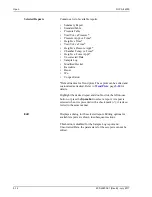
Page 84: ... is a new file you can accept this number or you can enter a name consisting of up to eight characters For parameter files displays an asterisk and a default extension ANC for analysis conditions RPO for report options If this is a new file enter a name in the File name field You can enter up to eight characters Status Date Range Directories Refer to Selecting Files page 2 10 for a description of ...

Page 85: ... Basic and Restricted Advanced Presents all parts of the sample information file in a tabbed dialog allowing easy access to each parameter Use this format to customize files Basic Presents the sample information file in a single dialog This format allows you to quickly create a sample information file using previously defined parameter files You also can switch to the Advanced format to view or ed...

Page 86: ...t file s description If this is a new file the description specified in sample defaults is displayed The sample file name number is shown in the example above because the dollar sign was used in Sample Defaults You may enter a new description or edit the existing one Range 50 alphanumeric characters Operator Submitter Enter the name of the operator who will be performing the anal ysis and the name...

Page 87: ...he recommended amount of sample to use Skeletal Density Enables you to enter the skeletal density also known as the true density of your sample Bulk Density Enables you to enter the bulk density sometimes referred to as pour density of your sample User Parameters The fields in this group box can be used for SPC Statistical Process Control reporting They are used to specify character istics of the ...

Page 88: ... by the analysis program to display in the Sample Log report You can make multiple entries by selecting this push button as many times as you wish Replace All Allows you to replace the values of the current sample file with those from an existing one A dialog is displayed so that you may select the file The values are copied into the file you may edit them as needed This replaces all parameters of...

Page 89: ...on If this is a new file the description specified in sample defaults is displayed You may enter a new description or add to the existing one Range 50 alphanumeric characters Replace All Allows you to replace the values of the current sample file with those from an existing one A dialog is displayed so that you may select the desired file After you have copied the values into the current file you ...

Page 90: ...edict COAN for Tread Hard carbons than for Carcass Soft carbons If you select Other the COAN is not calculated Choose Other only when your material is something other than Tread Hard or Carcass Soft Scan Rate Ending Pressure Recording Interval Use Prior Blank Measure Residual Volume Time Between Cycles These fields display the values and options for the selected Analysis Conditions file they may b...

Page 91: ...rmation on the Restricted format The Restricted format displays in the same manner as the Basic format Some menu functions however are disabled and you cannot switch to the Advanced format to edit file parameters Refer to Basic and Restricted Formats page 3 8 for step by step instructions for creating a Restricted sample information file The Restricted format does not contain an Advanced push butt...

Page 92: ...e Parameter Files Directory page 8 19 Analysis Conditions Displays the description of the current file If this is a new file the description specified in sample defaults is displayed You may enter a new description or add to the existing one Range 40 alphanumeric characters Replace Allows you to replace the values in the current file with those from an existing one After the values are copied into...

Page 93: ...ber must be higher than that used in the blank analysis Measure Residual Volume Allows you to measure the void volume of the compressed sample At the end of the compression cycle the upper piston withdraws and a single point measurement is collected This point defines the top of compressed sample and is used to calculate the residual void volume Time Between Cycles Enter how many minutes to wait a...

Page 94: ...page 8 19 Report Options Displays the description of the current file If this is a new file the description specified in sample defaults is displayed You may enter a new description or edit the existing one Use an intuitive description that will help you to recognize it for future use You may enter up to 40 alphanumeric characters Replace Allows you to replace the values in the current file with t...

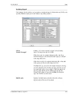
Page 95: ... tabular reports the Summary Report the Pressure Table Report and the void volume normalization Applied the force of the upper piston only Geometric Mean calculates a geometric mean of the applied upper piston and transmitted lower piston forces Normalize Void Volume Select this option to have the void volume normalized Overlays Displays the Graph Overlay Samples dialog Click Browse to choose the ...

Page 96: ...Default names for Trend plots These plots can be edited and customized as desired Refer to Trend Plots page 5 20 for details Highlight the desired report and double click the left mouse button or press the Spacebar to select a report A report is selected when it is preceded with a check mark it is dese lected in the same manner Edit Displays a dialog for the selected report Editing options for ava...

Page 97: ...pply to the selected material type are contained in the drop down lists If this file is not part of a sample information file all models in the system are shown in the drop down lists The Material type selected on the Sample Information dialog is used to determine which carbon property models are used for a particular carbon For example a different equation is used to predict COAN for Tread Hard c...

Page 98: ...ludes the residual top of the sample height the residual force measured on the lower load cell and the hold time Pressure Table Enables you to specify up to 999 pressure points at which to interpolate collected data less than 10 is typical Use the Insert Delete and Clear push buttons and Ctrl Down Arrow to assist you in creating your table Insert Inserts a line above the selected line Delete Delet...

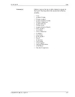
Page 99: ... contain the following variables Time Apparent Volume Pressure Applied Apparent Specific Volume Pressure Transmitted Apparent Density Pressure Mean Apparent Relative Density Force Applied Axial Strain Force Transmitted Void Ratio Force Mean Work Applied Height Work Mean Void Volume dV dP Applied Ambient Temperature dV dP Mean Chamber Temperature ...

Page 100: ...ly 2017 Standard Table The Standard Table report contains the data points collected during analysis and can display up to 8000 points You can display up to eight columns on the report The drop down lists contain the vari ables listed on page 5 17 ...

Page 101: ...to interpolate collected data Less than 10 is typical for most users Use the Insert Delete and Clear push buttons to assist you in creating your table Insert Inserts a line above the selected line Delete Deletes the selected line Clear Clears the table of all entries except one one is required Ctrl Down Arrow Appends a new line at the bottom of the table Column n Enables you to choose up to eight ...

Page 102: ...than or equal to 8000 every other data point will be displayed if the number of points is in the range of 8001 to 16000 and so forth X Axis Y Axis These drop down lists contain the variables available for the X and Y axes refer to page 5 18 Linear Logarithmic Enables you to plot the axes on a linear or logarithmic scale Overlay Contains choices for overlaying plots From this drop down list you can...

Page 103: ...The Sample Log report displays the following it cannot be edited Automatic operations Information entered using Add Log Entry on the sample file editor Warnings and or errors which occurred during analysis Plot curve Plot points Choose the manner in which data are plotted as a curve points or both Autoscale x axis Autoscale y axis Scales the X and or Y axes automatically Deselect Autoscale to ente...

Page 104: ...d later modified for compaction of powders where the porosity is substituted for concentration and pressure substituted for time Model Displays equation parameters for the modified Heckel model Options Applied reports the force applied from the upper piston only Mean reports the geometric mean of the force applied from the upper and lower pistons Pressure range the pressure range on which the mode...

Page 105: ...ange of pressures over which they are plotted although some may show curvature at the low pressure end Refer to Modified Heckel Report page 5 22 for an explanation of the fields on this dialog Plot curve Plot points Choose the manner in which data are plotted as a curve points or both Autoscale x axis Autoscale y axis Scales the X and or Y axes automatically Deselect Autoscale to enter a range in ...

Page 106: ...void ratio the minimum void ratio and the critical void ratio are pressure dependent Plotting the void volume porosity and or apparent density using the Bauer model provides a good fit for carbon black curves Refer to Modified Heckel Report page 5 22 for an explanation of the fields on this dialog ...

Page 107: ...he pressure and density dependency of soil For granular soils the stress response to a strain input depends explicitly of density and the tangen tial stiffness depends on pressure in a way which is weaker than linear Refer to Modified Heckel Report page 5 22 for an explanation of the fields on this dialog ...

Page 108: ... equation is based on the assumption that compression of powder is a process that takes place in two stages where stage 1 is filling voids and stage 2 is fragmentation and deformation of the particles Refer to Modified Heckel Report page 5 22 for an explanation of the fields on this dialog ...

Page 109: ...indow as a standalone parameter file For example select Analysis Conditions from the Save As menu to create a standalone parameter file of the analysis conditions portion of the active sample file Save All Saves all open files under their current names This option provides a faster way to save all open files at one time and avoids having to perform a Save operation on each individual file Close Cl...

Page 110: ... Files Directories These options are explained in Selecting Files beginning on page 2 10 Settings Enables you to choose output options Select the down arrow to the right of the Destination field to choose the destination Printer enables the Copies field allowing you to print up to four copies to a printer Screen prints the information to the screen File generates a text file which can be viewed wi...

Page 111: ...shows an Analysis Conditions file printed to the Screen Close Closes the dialog Print Prints the report to the default printer Header Toggles the header on and off Prev Next Enabled when the report contains multiple pages allowing you to advance to other pages Header ...

Page 112: ... created or last edited File identification File status The List dialog is common to all file types The title bar displays the type of file for which you have requested information File name If you select only one file from the Files list the name is copied to this field If multiple files are selected the last one selected displays in this field Status Date Range Files Directories These options ar...

Page 113: ... the right of the Destination field to choose the destination Printer enables the Copies field allowing you to print up to four copies to a printer Screen prints the information to the computer screen File generates a text file which can be viewed with a text editor or other text file manipulation tool Also enables the File name field so that you can enter a name for the file or you can accept the...

Page 114: ...alysis and the sample analysis are generated in eight columns Elapsed Time Height Applied Force Transmitted Force Applied Pressure Transmitted Pressure Chamber Temperature and Ambient Temperature Select File Export from the main menu the Export Sample File dialog is displayed File name Displays the name of the file you select from the Files list You can export multiple files by holding down Ctrl w...

Page 115: ... closes the file No discards the changes and closes the file Cancel returns to the open file Copies Enabled when you choose Printer as the destination allowing you to print up to four copies to a printer Destination Contains a list of output destinations you can print to a Printer to the Screen or to a File File name Enabled when you select File as the destination allowing you to enter a name or y...

Page 116: ......

Page 117: ...on the menu bar if the analysis program is being used for offline data manipulation Sample Analysis Perform a sample analysis Page 6 3 Reference Run Perform an analysis on the SRB reference materials Page 6 7 Return Upper Piston Home Return the upper piston to its home position Page 6 8 Return Lower Piston Home Return the lower piston to its home position Page 6 8 Clean System Clean the sample cha...

Page 118: ...ion of the operational window enabling you to view the status of the operation in progress Page 6 13 Show Instrument Log Display the instrument log Page 6 14 Unit Configuration Display the configuration of the analyzer Page 6 16 Diagnostics For service personnel only Page 6 16 Calibration Perform certain instrument calibrations with assistance from a service representative Page 6 17 Normalization ...

Page 119: ...tion You can skip the blank analysis if you check the Use Prior Blank option the data from the last blank analysis will be used Choose a file from the Open Sample Information File dialog or create a new one to display the Analysis dialog The fields now contain the values for the selected file or if creating a new file the specified defaults View Allows you to view the current operation the instrum...

Page 120: ...lace the values for all parameters of the current file with those from an existing file Analysis Conditions Displays a description of the analysis conditions file in the selected sample information file Use the drop down list to select a different Analysis Conditions file Report Options Displays a description of the report options file in the sample information file you have chosen for this analys...

Page 121: ...orts data automatically after the analysis displays the Export Settings dialog so that you can specify export output options User Parameters The fields in this group box can be used for SPC Statistical Process Control reporting They are used to specify character istics of the sample or its manufacturing process as well as to enter constants to be included in User Model formulae Once specified thes...

Page 122: ...s you to the Results window of the last analysis performed Start Begins the blank analysis After completion of the blank analy sis a dialog prompting you to load the sample is displayed If you chose Use Prior Blank this dialog displays when you select Start Load the sample close the shield press Reset and click OK to begin the analysis Do not click OK until you have loaded the sample and closed th...

Page 123: ...eference materials when you install a new piston tip Perform four reference runs on each reference material this will consist of 24 runs At the end of each reference run the Reference Run dialog is displayed allowing you to choose the appropriate reference material and start the next run Data from the runs can be viewed using the Normalization option refer to Normalization page 6 19 Reference Name...

Page 124: ...rns the lower piston to its home position the Return Lower Piston Home dialog is displayed The dialog closes automatically when the lower piston reaches its destination File Displays the sample file number numbers are assigned auto matically to reference runs Sample Displays the description assigned to the reference run By default this is the SRB series reference material name that was selected in...

Page 125: ... panel 4 Click Start on the Clean System dialog 5 When the cleaning process is complete all components return to a ready state and the dialog closes automatically 6 Remove the waste try and empty its contents 7 Wipe off the lower piston tip 8 Insert the sample tray 9 Press the Reset button on the instrument s front panel Start Starts the cleaning process The piston travels down the sample chamber ...

Page 126: ...ns is activated while the appropriate direction symbol is pressed with the left mouse button movement ceases when you release the mouse button Use one of the following options to move to the selectable components on the instrument schematic click on the component use the Tab key or arrow keys to move to the component A component is selected when it is surrounded by a dotted line Manual Control is ...

Page 127: ... the upper piston to the lower piston is displayed to the right of the piston icon Use the Up Down arrows on the right side to move the piston when manual control is enabled Represents the sample chamber The ambient temperature of the sample compartment upper and the temperature of the sample chamber lower are displayed to the left of the chamber Represents the lower piston and tray indicating it ...

Page 128: ... the instrument schematic These readings display to the right of the sample chamber A The applied force and pressure at which the upper piston presses against the lower piston B The transmitted force and pressure received by the lower piston Displays the speed at which the upper piston travels Right click on the icon to display its shortcut menu or press Shift F9 when the icon is selected Actions ...

Page 129: ...ile Sample File Displays the name of the current sample file Status Displays the status of the current operation or Idle if an opera tion is not in progress Height Displays the distance from the tip of the upper piston to the tip of the lower piston Pressure Displays the applied and transmitted pressures being applied by the piston Force Displays the applied and transmitted forces being applied to...

Page 130: ...etained in the Unit 1 section of the WIN4000 INI file Analysis Calibration Message Select the type of entries to display in the instrument log For example if you select Analysis only Analysis operations are displayed Add Log Entry Use this push button to enter analysis and or sample criteria not recorded automatically by the analysis program that you wish to display in the Instrument Log report Yo...

Page 131: ... Double click in the field or press F4 to display a calendar to choose a date Press F3 to insert the current date Copies Enabled when you choose Printer for the destination allowing you to print up to four copies Destination Specify a report destination you can print to the Screen Printer or a File File name Enabled when you select File for the destination enter a file name Use this set of left ri...

Page 132: ...romeritics service personnel Software Versions Displays the software versions for components being used by the analyzer and the serial number of the analyzer Cylinder run count Displays the number of piston cycles for the analyzer Upper Tip Run count Lower Tip Run count Displays the number of cycles for the upper and lower pistons Reset Enables you to reset the Tip run count fields to zero after t...

Page 133: ...cs service representative using the Service Test Mode refer to Service Test Mode page 8 19 Each dialog has the following push buttons Set Lower Piston Home Zeroes and sets the position of the lower piston the Set Lower Piston Home dialog is displayed If the Master switch on the rear panel is turned off the position of the lower piston is reset indi cated on the instrument schematic Use this comman...

Page 134: ... 01 Rev B July 2017 Upper Zero Force Zeroes the force of the upper piston Be sure the upper piston is raised to its uppermost position before beginning Zero Height Zeroes the piston height Lower Force Scale Scales the lower load cell reading ...

Page 135: ...rmalization window see example below is how well the software was able to determine the polynomials it will use to correct or normalize the collected data Include Last Choose the number of recent reference analyses you wish to include in the normalization Reference Analyses table Lists details of the files chosen in the Include Last field Data graphs Displays the Regression fit residuals for the G...

Page 136: ......

Page 137: ...ludes only data collected up to the time of the report Description Listed below are brief descriptions of the commands contained on the Reports menu Detailed descriptions are in subsequent sections Start Report Generate a report on a completed sample analysis or on the data collected thus far for an analysis in progress Page 7 2 Close Reports Close all open report windows Page 7 4 Open Report Open...

Page 138: ...e of the sample file you select from the Files list window If you have a sample file open its name defaults to this field If you select multiple files the reports specified in each sample file are printed to the output destination If you choose a single file the Select Reports dialog con taining the available reports is displayed This dialog al lows you to select the reports you wish to generate ...

Page 139: ...s a drop down list of output destinations Printer reports are generated to your default printer Screen reports are displayed onscreen File tabular reports are converted to a text file which can be viewed with a text editor or other text file manipulation tool File name Enabled when you select File as the destination Allows you to enter a name or you may accept the default Files list window Display...

Page 140: ...o select Close on each report window This option is unavailable if reports are being generated Open Report This option enables you to open a report that was saved from the Report window the Report window opens with an Open dialog positioned on top Navigate to the desired directory select your file and click Open your saved report is displayed in the Report window ...

Page 141: ...ilable for SPC reporting You can check as many as you wish however for efficiency it is best to select only the variables you actually intend to use All variables selected must be computed for each sample file used in an SPC report If you select an option that requires an entry the adjacent field is enabled allowing you to enter a value ...

Page 142: ... For example you may wish to display your company logo The graphic must be a bitmap bmp or enhanced metafile emf Click Browse to choose the file use the Height and Width fields to specify a size This image can be edited or removed in the report window if printed to the screen X and Y Axes Variable fields Allows you to designate the X and Y axes variables Click on the down arrow to display a list o...

Page 143: ...the SPC Report Options are included in the new report however it does lengthen the time required to generate the report Tabular report Generate tabular as well as graphical data of the included samples A tabular report contains the numeric values contributed by each sample Label data Allows you to label the points on the plot to correspond with the values in the sample files Samples Displays the R...

Page 144: ...irectory Use the directory window to navigate to a different directory Refer to Selecting Files page 2 12 for information on selecting different directories Add Moves the selected file in the Available Files pane to the Selected Files pane Alternatively you can simply double click on the desired files You can select multiple files by holding down Ctrl while making your selections You can include u...

Page 145: ... title For example you may wish to display your company logo The graphic must be a bit map bmp or enhanced metafile emf Click Browse to choose the file then use the Height and Width fields to specify a size This image can be edited or removed in the report window X axis Order By Enables you to choose the order in which X axis statistics are placed Time places the files on the graph at numerical po...

Page 146: ...have elapsed from the first file placed on the list which the earliest analyzed file Graph n Displays the Control Chart Graph n Options dialog allowing you to define the Y axis of each graph Statistic This drop down list displays the SPC variables selected on the SPC Report Options dialog The variable you choose will be plotted against the variable chosen for the X axis Autoscale Scales the Y axis...

Page 147: ...amples A tabular report contains the numeric values contributed by each sample Recalculate archived SPC results Select this option to have archived SPC values recalculated This ensures that any changes made to the SPC Report Options are included in the new report It also lengthens the time required to generate the report Samples Displays the Control Chart Sample Selection dialog for you to choose ...

Page 148: ...he current definition of the report as the default Report Settings The options in this group box enable you to choose output criteria The Copies field is enabled when you choose Printer as the destination enabling you to print up to four copies of the report Report Generates the report ...

Page 149: ...al number date and time of analysis analysis conditions and so forth Headers also contain notes of any changes to the sample file that occur after analysis Summary reports also contain parameters for the blank analysis when requested Compaction reports also contain the calculated parameters of the applicable equation as well as the RMS error This example shows a typical report header ...

Page 150: ...he report header To view a specific report select its tab or select the report in the Reports window and click Show You can resize the header pane or the data pane using the double arrow obtained when placing your cursor at the bottom of the bar separating the two panes This allows you to hide the header if desired Scroll bars are provided on both panes for scrolling through pane contents You can ...

Page 151: ... become visible Delete Deletes the selected report The deleted report s will have to be regenerated if deleted in error Hide Hides removes the selected report from the report window The report s associated tab is also removed Open Opens a previously saved report file Print Displays a print dialog so that you can choose a printer for report output A list of available reports is displayed in the win...

Page 152: ...ort window Shown prints only the shown reports any nonhighlighted reports indicate they are hidden You can still select hidden reports from this window to print All prints all reports including those that may have been hidden Clear clears all selections Save Saves all reports of the currently open file in a report format using the same name as the sample file only with an rep extension If you wish...

Page 153: ... Open Report command Spreadsheet xls Saved in a format which can be imported into most spreadsheet programs Ascii Text txt Saved in ASCII text which can be imported into programs accepting this type of file Default Style Displays the Default Style dialog so that you can specify default parameters for report fonts and curve properties Font Contains a list of report elements for which the font can b...

Page 154: ...Close Closes the Default Style dialog and applies the changes If you clicked Save the changes become the defaults If you did not click Save the changes apply only to the current report set Close Closes the report window Resize column Specify the width of the selected column in inches Rename column Edit the name of the selected column Use Ctrl Enter to insert line feeds Move column Move the locatio...

Page 155: ...ttributes for column headers in the current report Edit title Edit the table title and font Copy table as text Copy the entire table column headers and data and insert it into another program Columns are tab delimited allowing easy alignment Autoscale Autoscales all axes of the graph This function is useful for returning to a full view after zooming Redraw Sets axis boundaries to its original view...

Page 156: ...n which collected data can be displayed Choices Curve Histogram Points Curve and Points Curve group box Edit the curve interpolation the style of curve and or points and the pen color The options in this group box are disabled if Histogram is chosen in the Style drop down list Histogram group box Allows you to specify the type of fill and the color if Histogram is chosen as the style for collected...

Page 157: ...t the placement of the legend Edit title Displays the Title Properties dialog allowing you to edit the current graph s title and font Copy as metafile Copies the graph and places it on the clipboard allowing you to paste it into other applications accepting Windows metafiles Copy as text Copies the data used to generate the graph as a series of tab delimited columns of text Select this option to r...

Page 158: ...zoom in to examine fine details To use this feature hold down the left mouse button and drag the mouse cursor drawing a box across the area you wish to view then release the button The enlarged area immediately fills the graph area Right click in the graph area and choose Redraw or Autoscale from the shortcut menu to return to the normal view ...

Page 159: ... the graph Right click in the graph area and choose Redraw or Autoscale from the shortcut menu to remove cross hair lines and return to the normal view Alternatively you can click outside of the graph area Time s 0 0 50 100 150 200 250 300 153 Height in 1 0 1 0 1 5 1 07 Apparent Density g cm 0 5 0 5 1 0 0 60 Height vs Time Height vs Time Apparent Dens vs Time X axis position Point of Coordination ...

Page 160: ......

Page 161: ...rameter files Access the service test mode to perform calibrations Description Option Presentation Allows you to display the sample file dialog in Advanced Basic or Restricted format Page 8 3 Sample Defaults Specify defaults for the parameters contained in the sample information and parameter files Page 8 6 Reference Table Specifies the void volume range for SRB Standard Reference Black reference ...

Page 162: ...and Y axes Page 8 13 Live Graph Choose the variable for the X axis during data collection Page 8 18 Parameter Files Directory Specify a different location for the predefined parameter files used by the Basic and Restricted formats Page 8 19 Service Test Mode Enables you to perform certain troubleshooting procedures This option is available only under the direction of a Micromeritics service repres...

Page 163: ... or Restricted format Advanced The Advanced format presents all parts of the sample information file in a tabbed dialog Click the tab or use Next and Prev to access the parameters The Advanced format is used to create customized sample files You can also switch to the Basic format if desired by clicking Basic Refer to Advanced page 5 4 for a detailed description of this dialog ...

Page 164: ... the sample information file and its parameter files in a single dialog This format is used to create sample information files using previously defined parameter files You can easily switch to the Advanced format by clicking Advanced Refer to Basic page 5 7 for a detailed description of this dialog ...

Page 165: ...1 characters can be used to enable the Restricted format The same pass word must be used to exit the Restricted format For example if you enter password to enable the Restricted format then you must use password to exit If you forget the password open the WIN4000 INI file and navigate to the Private section The current password will be shown immediately following OptionPresentationPassword Make a ...

Page 166: ...ach parameter The values you specify in the parameter portions Analysis Conditions and Report Options of the sample file are saved as the defaults for newly created parameter files For example after specifying defaults for a sample file in the Advanced format Select File Open Sample Information then click Yes to create the file and the defaults you specify display for all parameters Select File Op...

Page 167: ...lone In the field on the left edit the prompt for Sample if desired For example you may prefer to use Test or Material You can use up to 20 characters In the field on the right specify a format for the sample identi fication Or leave this field blank and enter identifications as files are created Use numbers letters or other printable characters such as dashes Use up to 42 characters including the...

Page 168: ...from displaying on the sam ple file dialog Bar Code This field enables you to enter bar code information If bar code information is not used you can use this field to enter additional information about the sample for example you may wish to enter the lot number of your sample This field as well as other fields on the dialog accepts data from a bar code reader A bar code reader can be attached to o...

Page 169: ...event them from displaying on the sample information dialog Material Properties Enter the type of sample material you are analyzing The Material type is used to determine which carbon property models are used for this particular carbon For example a different equation is used to predict COAN for Tread Hard carbons than for Carcass Soft carbons If you select Other the COAN is not calculated Choose ...

Page 170: ...nditions page 5 10 Report Options page 5 12 Basic The dialog for the Basic format contains all parameters on one screen The defaults you specify for the Basic format also serve as the defaults for the Restricted format Replace All Replace the contents of all parameters in the current default sample file with those from an existing sample file For example you may have an existing sample file that c...

Page 171: ...information than the sample file name alone In the field on the left edit the prompt if desired For example you may prefer to use Test or Material The maximum number of characters is 20 In the field on the right specify a format for the sample identification Use numbers letters or other printable characters such as dashes Use up to 42 characters including the symbol if used Include the automatical...

Page 172: ...ch carbon property models are used for this particular carbon For example a different equation is used to predict COAN for Tread Hard carbons than for Carcass Soft carbons If you select Other the COAN is not calculated Choose Other only when your material is something other than Tread Hard or Carcass Soft Scan Rate Ending Pressure Recording Use Prior Blank Measure Residual Volume Time Between Cycl...

Page 173: ...the SRB reference number or name Class Indicates the type of reference material Tread Hard or Carcass Soft Void Volume Displays the void volume range Insert Allows you to add reference materials to the list of defaults Click the down arrow at the end of the field to display a list of reference materials Delete Removes the selected reference material from the list You can add it back to the list us...

Page 174: ...rves based on your own experimentation The calculation results will appear on the Summary Report when selected Material Displays the type of material Model Name Displays the name of the model Formula Displays the formula to be used for the model Insert Displays the Model Table Edit dialog Material Enter the name of material to be associated with this model ...

Page 175: ... an applied pressure two identical forms are provided e g Height and HeightA Collected data functions Height applied pressure in MPa cm HeightA applied pressure in MPa cm HeightM geometric mean pressure in MPa cm Work applied pressure in MPa cm3 g WorkA applied pressure in MPa cm3 g WorkM geometric mean pressure in MPa cm3 g VV applied pressure in MPa cm Newton VVA applied pressure in MPa cm Newto...

Page 176: ... user parameters must match the ones specified in the sample default file When entering a formula you can enter constants with the names of the user parameters defined in the sample defaults file refer to Sample Defaults page 8 6 When calculating the value for the formula the software will look up the user parameter with that name in the sample file If it does not exist then the formula will not b...

Page 177: ...hich to display pressure force and length the Units Selections dialog is displayed Load from File Displays the Select User Model File dialog allowing you to load a model file saved in text txt format Save to File Save the selected model to a text file Refer to the dialog shown above ...

Page 178: ...ph This option enables you to change the view of the graph during data collection You can change the x axis to scale data on a Linear Scale or Logarithmic Scale X Axis Y Axis Choose Major and or Minor lines to display in printed reports for the Logarithmic and Linear scales Grid lines are not shown if these items are not selected Grid Line Style Choose the type of grid line to display ...

Page 179: ...udes several parameter files supplied with the analysis pro gram If you specify a different directory these files will not be included in the drop down lists unless you copy or move them to the new directory If you wish to continue to use the param directory for parameter files it displays as the default when saving parameter files Service Test Mode Calibration procedures are included in the DVVA ...

Page 180: ......

Page 181: ... are described in the following table Table 9 1 Common Operational Problems Problem Cause Solution Fault indicator will not turn off Safety shield is not completely closed Slide the safety shield all the way down Drawer is open Close the drawer The Emergency Stop button is engaged Turn the Emergency Stop button to the right to release it then press Reset The USB cable was discon nected and reconne...

Page 182: ...of sample for all analyses All samples were not prepared in the same manner Use the same preparation method for all samples The piston tip is not securely affixed to the piston Moderately tighten the tip using a 3 8 in wrench The upper or lower piston tip is dirty Wipe the piston tips with a Kimwipe or paper towel between each blank analysis and each sample analysis The piston tip is damaged Repla...

Page 183: ...oderately tighten the lower piston tip The lower piston tip is worn or damaged Replace with a new tip The wrong tray is inserted in the analyzer Insert the correct tray Readings in the instrument schematic display all zeros The DVAA II 4000 was not recognized by Windows preventing the data acquisition drivers from loading Perform Full Power On Procedure on page 9 4 Piston will not move Manual cont...

Page 184: ...nt MAIN POWER switch on back panel is in the OFF position c The instrument Power switch on the front panel is in the OFF position d The USB cable is disconnected from the instrument 2 Place the instrument MAIN POWER switch on the back panel to the ON position 3 Connect the USB cable to the instrument 4 Turn on the computer 5 If required allow Windows to install the drivers for any new hardware fou...

Page 185: ...when the computer needs to be shut down for an extended period of time 1 Exit the DVVA II 4000 software 2 Place the power switch on the front panel of the instrument in the OFF position 3 Disconnect the USB cable from the instrument 4 Place the instrument MAIN POWER switch on the back panel in the OFF position Upper load cell Lower load cells Linear height transducer If accessibility to the back p...

Page 186: ...e drivers that were placed on the computer during the DVVA II 4000 software installation Problem The instrument schematic in the DVVA II 4000 software is showing 0 0 readings as shown below This is caused by Windows not detecting the USB data acquisition device Perform Action 1 below If this does not correct the problem follow the Actions below in sequence until the instrument is reconnected to th...

Page 187: ...3 1 Perform the Full Power Off Procedure described on page 9 5 2 Exit Windows and shut down the computer 3 Unplug the USB cable at the computer wait about 10 seconds and then plug into a different port in the computer 4 Perform the Full Power On Procedure described on page 9 4 Windows should automatically load new drivers due to the new port If not perform the device driver installation described ...

Page 188: ... correct the problem perform Action 2 Action 1 1 Ensure that the upper piston is in the raised position If it is not select Unit 1 Schematic then Unit 1 Enable Manual Control to display the Manual Control screen Use the icon next to the upper piston to raise it to its home position Once the instrument is functioning properly do not turn off the computer power switch or the DVVA MAIN POWER switch l...

Page 189: ...the safety shield is not already raised raise it to its upper position 3 Retrieve the pellet removal tool shown below that was included in the instrument accessories kit 4 Carefully place the tool into the compression chamber and while applying pressure rotate the tool ...

Page 190: ...ould decline as shown below When the lower load cell force has fallen to approximately 230 kg 500 lbs remove the tool and manually move the lower piston downward until it reaches its home position using the icon 6 If the lower piston moves to its home position a Close the safety shield b Press the Reset button c Proceed to Step 7 Lower piston manual control Lower load cell force ...

Page 191: ...ng steps 4 and 5 the piston cannot be moved to its home position a Close the safety shield b Press the Reset button c Proceed to Action 2 on page 9 12 7 Select Unit 1 Clean System from the main menu to clear the compressed pellet from the compression chamber 8 The DVVA II should now be operational ...

Page 192: ... the problem you can manually release the piston as described below 1 Support the lower front panel from the bottom and remove the four screws shown in the photograph below 2 Remove the panel and set it aside Never override the instrument panel sensor or operate the instrument with the panel removed ...

Page 193: ...ews 6 Close the safety shield 7 Press the Reset button on the instrument 8 Select Unit 1 Return Lower Position Home from the main menu 9 Ensure that no foreign debris has fallen into the compression chamber While the expandable cover is removed ensure that no foreign matter is allowed to enter inside the cover Also avoid disturbing any grease found on the screw thread Be careful when releasing the...

Page 194: ...leshooting DVVA II 4000 9 14 400 42803 01 Rev B July 2017 10 Select Unit 1 Clean System from the main menu to clear the compressed pellet from the compression chamber 11 The DVVA II should now be operational ...

Page 195: ...d window cleaner Use a paper towel or Kimwipe or paper towel to clean the piston tip never use a solvent You may use a vacuum cleaner on the sample and waste trays Do not use detergent or other cleaners on the moving components of the instrument Perform a full power off procedure before you clean around any of the connectors on the rear panel of the instrument refer to page 9 5 Then perform a full...

Page 196: ...eplacing the Upper Piston Tip 1 Select Unit 1 Return Upper Piston Home to move the piston to its uppermost position completely out of the sample chamber 2 Slide the sample compartment shield to its uppermost position 3 Place a stiff piece of paper or cardboard over the top of the sample funnel to prevent the loosened tip from accidentally falling down into the chamber Upper piston home position ...

Page 197: ...left to loosen and remove the piston 5 Install a new piston tip Using the same wrench moderately tighten the piston tip 6 Select Unit 1 Unit configuration to display the Unit configuration dialog 7 Click the Reset buttons to reset the Upper Tip Run count to 0 zero then click OK to close the dialog ...

Page 198: ...nd remove the piston in the sample tray 3 Install a new piston tip Using the same wrench moderately tighten the piston tip 4 Replace the lower piston tray and press the Reset button on the analyzer 5 Select Unit 1 Unit configuration to display the Unit configuration dialog 6 Click the Reset buttons to reset the Lower Tip Run count to 0 zero then click OK to close the dialog ...

Page 199: ...n Down arrow until the pressure display shows 1000 lbf or greater 6 Return the lower piston to its lowest position 7 Select Unit 1 Return Upper Piston Home to return the piston to its uppermost position 8 Select Unit 1 Enable Manual Control to remove the check mark and disable manual control 9 Minimize or close the instrument schematic Use of certain USB devices or the addition or removal of a USB...

Page 200: ...h the Open Sample Information dialog positioned on top 13 Click OK to accept the next sequenced number in the File name field the Analysis dialog containing file defaults is displayed 14 Click Replace All and select the file named COND smp then click OK All appropriate values will be inserted into the dialog fields 15 Edit the description in the Sample field by adding a 1 indicating this is the fi...

Page 201: ... to begin the analysis a dialog showing data as collected is displayed 18 After the blank analysis is complete a dialog prompting you to add sample is displayed Do not click OK until you have placed the sample in the chamber The piston automatically returns to the home position at the completion of the blank analysis ...

Page 202: ...DVVA II 4000 9 22 400 42803 01 Rev B July 2017 19 Slide the sample compartment shield up wipe the piston tip with a Kimwipe or paper towel 20 Pour the sample into the sample chamber and close the shield press Reset ...

Page 203: ...osition when the analysis is finished 22 Slide the shield up and wipe the piston tip with a Kimwipe or paper towel then close the shield press Reset 23 Click Next on the Data Collection view of the Analysis dialog to return to the first view of the Analysis dialog 24 Click Browse the Open Sample Information dialog is displayed 25 Click OK to accept the next sequenced number in the File name field ...

Page 204: ...each blank analysis and sample analysis 28 Advance to Overlaying Results to determine if the piston is sufficiently conditioned Overlaying Results When results start to be consistent the piston tip is sufficiently conditioned Perform the follow ing steps to overlay the results from the last six analyses 1 Select File Open Sample Information and choose the fifth file of the condition series 2 Click...

Page 205: ...h Overlay dialog is displayed 6 Click Browse to the right of the first five Sample n fields and select the remaining files used in the conditioning procedure 7 Click OK to return to the Report Options dialog 8 Click Save on the Report Options dialog do not close the dialog 9 Click Reports Start Report the Start Report dialog is displayed Note that the number of your open file defaults to the File ...

Page 206: ...he graph 5 000 15 000 and 25 000 psi Continue zooming on each until you can determine if the curves for three sequential runs are within 0 001 inch If the curves are not within this range repeat analyses until three sequential curves are obtained If after a total of 20 analyses you still have not obtained these results Refer to Table 9 1 Common Operational Problems page 9 1 for corrective solution...

Page 207: ... runs each are sufficient for maintaining normalization When you replace the piston tip you should perform four runs each This will be a total of 24 runs when a new tip has been installed 1 Perform two blank analyses as described in steps 1 through 16 under the heading Replacing and Conditioning the Piston Tip on page 9 16 2 Prepare two samples of one of the reference materials prepare according t...

Page 208: ...Normalization DVVA II 4000 9 28 400 42803 01 Rev B July 2017 4 Select Unit Reference Run the Reference Run dialog is displayed 5 Enter the sample mass in the Mass field ...

Page 209: ...eference material into the sample chamber c Wipe the piston tip with a Kimwipe or paper towel d Close the sample shield and press Reset e Click OK on the Load Sample dialog to begin the reference run 10 When the analysis has completed the Start push button on the dialog changes to Next Click Next to return to the original view of the Analysis dialog Bulk Density for SRB Reference Materials Referen...

Page 210: ...0 42803 01 Rev B July 2017 11 Perform the following steps a Open the sample shield b Wipe the piston tip with a Kimwipe or paper towel d Close the sample shield and press Reset 12 Complete steps 1 through 10 for all reference materials ...

Page 211: ...rent analysis has shifted from that average The nor malization routine calculates a set of polynomials to correct for that difference What is shown in the Normalization window see example below is how well the software was able to determine the polynomials it will use to correct or normalize the collected data 1 Select Unit Normalization the Normalization dialog is displayed 2 Note the residual va...

Page 212: ......

Page 213: ...r web site at www micromeritics com Contact your local sales representative When ordering please use the information provided below to place your order Part Number Item and Description 400 25808 00 Piston tip assembly 1 2 in 004 24046 01 Scale pan for weighing sample 004 54617 00 Brush for dusting any remaining sample from the sample container into the chamber 004 54010 00 Wrench 3 8 x 7 16 open e...

Page 214: ......

Page 215: ... Start Report failed to execute the report subsystem which is a separate process Action Restart the computer If the problem persists reinstall the application this will not affect any of your sample files If the problem continues contact a Micromeritics service representative Cause An internal processing and or hardware error has occurred Action Contact your service representative if you continue ...

Page 216: ...ssing and or hardware error has occurred Action Contact your service representative if you continue to receive this error message Cause Several files sample information or parameter files have been added to this directory by some function other than the DVVA II program Action Select Yes to update the directory information with data from each new file This operation may take a minute Select No if y...

Page 217: ... and or extension Action Type a valid path name including the proper extension and press Enter Cause You entered a file specification that does not exist Action Enter an existing file specification or select a file name from the list box Cause You entered an invalid path name and or extension Action Type a valid path name including the proper extension and press Enter Cause An unexpected error occ...

Page 218: ...ocessed Please reselect the remainder Cause You entered an invalid file name Action See the description of file naming conventions in your Windows man ual and re enter the name Cause You are in the process of initiating an automatic analysis an analysis in which sample files are created using the defaults while editing the defaults Action Finish your edit session of the defaults and close the dial...

Page 219: ...Cause You have more than 50 files open at the same time Action Refer to the manual for your operating system and set the limit for open files to 50 or greater Cause You have too many windows open in the application Action Close some of the open windows Cause You attempted to exit the application while the analyzer is performing a critical operation This operation must be completed before the appli...

Page 220: ...act your service representative Cause The initialization of the analyzer configured with the Set Up program has failed The application stops Action A Usually this message is preceded by another message giving the reason for the analyzer s failure to initialize See the instructions for that mes sage Action B Check the cable connection between the analyzer and the computer Verify that the analyzer h...

Page 221: ...essed Action C Contact your service representative Cause You are attempting to open a file that is currently being used either by this application or another Action Locate the application using the file in the Micromeritics application use the Windows menu item to get a list of all windows one of which may contain this file Cause You attempted to use a sample file containing errors that is current...

Page 222: ...r hardware error has occurred Action A Contact your service representative if you continue to receive this error Cause The file you specified is being used in another edit operation Action Check the Windows list to locate the other edit session Cause The file you specified in a Save As operation is already open for edit Action Select a different file for the Save As operation Cause The ASCII INI f...

Page 223: ...he error Cause This field requires a valid entry for you to proceed Action Enter or select an appropriate value Cause The value you entered in the highlighted field is outside the valid range of values Action Check the entry and enter or select an appropriate value Cause The number you entered in the highlighted field is invalid Action Check the entry and enter or select a valid number Cause You e...

Page 224: ...y entered file name sequence number Action Select Options Sample Defaults from the Main Menu and enter a new sequence number Cause A large number of windows is open and consuming the system resources available to all applications Action Close one or more windows Contact your service representative if you continue to receive this message Cause An error occurred in the file being written to during a...

Page 225: ...that the file specified as an overlay does exist Cause An error occurred while the program was opening a file necessary to the report operation Action Use the name given in the error message to investigate Contact your service representative if you continue to receive this error message Cause A One or more data entry fields in the sample file may contain an invalid character such as a single quote...

Page 226: ...ore printing of the requested report has been canceled Action Delete unnecessary files from the disk You will require at least five megabytes of free space for normal operation Cause The requested print job was canceled at your request Action None required Cause You selected an invalid calibration file or one that cannot be read Action Be sure the media containing the calibration file has no probl...

Page 227: ...our local Micromeritics service representative Cause The application s control file has been corrupted or deleted Action Reinstall the analysis program Cause An internal processing and or hardware error has occurred Action Contact your service representative if you continue to receive this error message Cause The application has discovered a different version of software operat ing in the analyzer...

Page 228: ...print output Action Ensure that sufficient space is available on the drive containing the file Cause You attempted to exit the application while an analysis is in progress Action If you are not concerned with cancellation of the analysis click Yes to continue the exit otherwise select No and allow the analysis to finish Cause You were unable to open the online manual Action Exit the application an...

Page 229: ...act your service representative Cause A You attempted to open a file that is already open possibly minimized Action A View the minimized icons locate and maximize the file Cause B A computer or network problem occurred Action B Check the performance of your computer devices or network Cause C A software error occurred when the file was accessed Action C Contact your service representative Cause Yo...

Page 230: ...fferent file Cause You attempted to start an analysis using a file that contains errors and is open for editing Action A Finish editing the file save and close it or choose a different file Then restart the analysis Cause You attempted to start an analysis using a file that contains unsaved changes and is still open Action Click Yes to save the changes and proceed with the analysis Click No to can...

Page 231: ...use You requested a report for a file that does not contain collected data Action Choose a file that contains collected data Complete status Cause The lower piston cannot drive to the requested position Action Contact your service representative Cause You attempted to move the lower piston but its load is too high Action Raise the upper piston so that it is not pressing against the lower one Cause...

Page 232: ...ndamaged Cause The upper piston tip is damaged Action Replace the upper piston tip then repeat the calibration Cause The upper piston tip contains sample or debris Action Select Unit Clean System to clean the system then repeat the cali bration Cause A The chamber was not empty for the blank analysis Action A Repeat the analysis starting with a clean empty chamber Do not load sample until prompted...

Page 233: ...d and repeat the calibration Cause B The length of the calibration standard was not entered correctly Action B Enter the length stamped on the calibration standard Cause C A piston tip is damaged or very dirty Action C Clean or replace the piston tip Cause A Debris is in the chamber Action A Select Unit Clean System to clean the system The chamber should be empty for the blank analysis Do not load...

Page 234: ...tions is within the specification for your instrument If it is then call your service repre sentative Cause One of the safety interlocks was triggered Action A Ensure that the safety shield for the sample compartment is completely down and that the disposal drawer is completely closed Then press the Reset button Action B Turn the red Emergency Stop button clockwise to reset it then press the Reset...

Page 235: ...libration data has failed due to possible media problems Action A Confirm the media containing the calibration file has no problems Action B Choose an alternate media to Save the calibration data Cause You loaded a calibration file that was created for a different unit Action A Load a file that was created for the current unit Action B Contact your service representative for assistance in calibrat...

Page 236: ...Force Scale calibration the upper load cell is calibrated properly Action B Make sure the reference load cell has been tared properly and is dis playing the correct units Cause C Instrument failure Action C Contact your service representative Cause A Sample was in the chamber when the blank analysis was performed Action A Select Unit Clean System then retry the analysis Do not load sample until pr...

Page 237: ...ll other applications when performing an analysis Cause C A scheduled update was being performed while analysis data were being collected ActionC Schedule automatic updates during a time when analyses are not being performed for example during non working hours Cause D The hardware configuration of the computer was changed during anal ysis Action D Do not add or remove devices such as USB drives d...

Page 238: ...resentative Cause A The sample tray containing the lower piston was not in place when the analysis was started Action A Lower the lower piston open the tray drawer and install the sample tray Cause B The upper or lower piston does not have a proper calibration Action B Contact your service representative Cause A The sample tray containing the lower piston was not in place when the analysis was sta...

Page 239: ...d on the upper piston is higher than expected for the given oper aiton Action A Check for obstructions and ensure that the upper piston tip is clean If the error persists replace and condition the upper piston tip Cause B The upper piston is misaligned with the sample chamber Action B Contact your service representative Cause The measured line voltage is outside of the acceptable range Action Ensu...

Page 240: ......

Page 241: ...ear calibration One point F1 V1 is measured with no applied force so F1 0 The other F2 V2 is measured with an applied force The piston height as a function of linear transducer voltage is also found by a two point linear cal ibration One point h1 V1 is measured with an empty chamber so h1 0 The other h2 V2 is measured with a reference standard of known height h2 in the sample chamber where F measu...

Page 242: ... the sample chamber and for the deflection of the linear transducer where F applied force FS force on sample Ff frictional force hb bed height h measured height hd deflection Void Volume where VA apparent volume Fs force of sample hb bed height m mass S skeletal density d diameter of sample chamber FS F Ff hb hb h hd F VV FS VA FS VT 100 VA FS hbA A d 2 4 VT m S ...

Page 243: ...etal density ρs Vv Volume of the voids VT VS Void Ratio Porosity Kawakita The Kawakita is given by where P applied pressure C relative volume decrease a b material characteristic constants derived from a linear fit of V0 initial volume V volume at pressure P Bauer The Bauer equation is given by e VV VS VT VS VS S 1 n VV VT VT VS VT 1 S P C 1 ab P a V0 V V0 P C vs P e e0 3P a b exp ...

Page 244: ...ume at P VS volume of the solid sample P applied pressure a1 a2 material characteristic constants b1 b2 material characteristic constants The terms on the right hand side of the equation relate to the processes of particle rearrangement and particle deformation The constants b1 and b2 represent the pressures required to induce com paction due to those processes while a1 and b2 indicate the relativ...

Page 245: ... void ratio e0 void ratio at P 0 P applied pressure a b constants References The Kawakita Heckel and Cooper Eaton equations are discussed in the following 1 Kmio Kawakita and Yuhbun Tsutsumi A Comparison of Equations for Powder Compression Bulletin of the Chemical Society of Japan 39 1364 1368 1966 2 Patel and Patel Overview of Phenomenological Equations for Powder Compaction Study International J...

Page 246: ......

Page 247: ...8 Tread Hard 0 41 B 8 Tread Hard 0 31 C 8 Tread Hard 0 29 D 8 Carcass Soft 0 64 E 8 Carcass Soft 0 44 F 8 Carcass Soft 0 34 Reference Name Bulk Density A 7 Tread Hard 0 44 B 7 Tread Hard 0 32 C 7 Tread Hard 0 30 D 7 Carcass Soft 0 65 E 7 Carcass Soft 0 43 F 7 Carcass Soft 0 31 Reference Name Bulk Density A 6 Tread Hard 0 31 B 6 Tread Hard 0 34 C 6 Tread Hard 0 46 D 6 Carcass Soft 0 48 E 6 Carcass ...

Page 248: ......
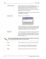
Page 249: ...r 3 2 3 7 5 5 8 8 Basic format 8 4 creating sample file 3 8 sample file defaults 8 10 Sample information file 5 7 specifying defaults for 3 1 Bauer report 5 24 calculations B 3 Bitmap graphic in report header 5 13 Blank analysis 6 3 Blank correction calculations B 2 C Calculations B 1 Bauer report B 3 blank correction B 2 Cooper Eaton B 4 Kawakita B 3 Modified Heckel report B 4 void volume B 2 Cal...

Page 250: ...porting sample files 5 32 F Fault indicator 2 1 troubleshooting 9 1 File opening 2 7 printing to 7 3 selecting 2 10 status 2 11 File menu 5 1 Exit command 5 33 Export command 5 32 Open command 5 2 Print command 5 28 Save As command 5 27 File name default extensions 2 13 included as part of ID 8 7 8 11 sequence 8 11 Formula for user models 8 15 Front panel 2 1 Function keys See Shortcut keys G Grap...

Page 251: ...command 8 3 Parameter Files Directory command 8 19 Reference Table command 8 13 Sample Defaults command 8 6 Service Test Mode 8 19 Units command 8 17 Ordering information 10 1 Overlay Graph overlay 3 27 multiple graphs 3 29 multiple samples 3 27 Overlays push button 5 13 P Parameter files 3 9 5 3 Analysis conditions creating 3 10 creating 5 2 defaults 8 6 directory 8 19 listing file statistics 3 2...

Page 252: ...ing 7 4 Pressure Table 5 19 Regression 7 6 Sample Log 5 21 saving 7 16 saving in other formats 7 17 selecting 2 12 Standard table 5 18 starting 2 7 Statistical Process Control SPC 7 5 Summary 5 15 Tabular editing onscreen 7 18 title showing 5 12 Tool bar 7 15 Uncorrected Data 5 21 Wu 5 25 zoom feature 7 22 Report button 7 8 Report Options dialog 5 12 Report options file 5 12 creating 3 11 listing ...

Page 253: ...Analysis program 4 1 installing upgrade 4 12 uninstalling 4 19 using 2 6 using for offline data reduction 4 1 version 2 15 6 16 SPC report user parameters 5 5 6 5 8 9 SPC Report Options command 7 5 SPC Report Options dialog 7 5 Specifications 1 4 1 5 Spreadsheet format saving reports 7 17 Standard Table report 5 18 Start Report command 7 2 Start Report dialog 7 2 Status drop down list 2 11 Status ...

Page 254: ... July 2017 V Version software 2 15 6 16 View drop down list 6 3 Void volume 5 11 8 13 calculations B 2 Voltage selector 2 3 W Warning defined 1 2 label 2 5 Windows menu 2 15 Wu report 5 25 calculations B 5 X X axis order by 7 9 Z Zoom feature 7 22 ...

Reviews: