


73
4
PARAMETERS
4.2.3 Base frequency, base frequency voltage (Pr. 3, Pr. 19, Pr. 47)
Pr. 3 "base frequency"
Pr. 19 "base frequency voltage"
Pr. 47 "second V/F(base frequency)
Used to adjust the inverter outputs (voltage,
frequency) to the motor rating.
When running a standard motor,
generally set the rated motor frequency.
When running the motor using the commercial power supply-inverter switch-over, set
the base frequency to the same value as the power supply frequency.
If the frequency given on the motor rating plate is "50Hz" only, always set to "50Hz".
Leaving it as "60Hz" may make the voltage too low and the torque less, resulting in
overload tripping. Care must be taken especially when Pr. 14 "load pattern selection = 1.
<Setting>
• Use Pr. 3 and Pr. 47 to set the base frequency (rated motor frequency). Two base
frequencies can be set and the required frequency can be selected from them.
• Pr. 47 "second V/F (base frequency)" is valid when the RT signal is on. (Note 3)
• Use Pr. 19 to set the base voltage (e.g. rated motor voltage).
Parameter
Number
Factory
Setting
Setting
Range
Remarks
3
60Hz
0 to 400Hz
19
9999
0 to 1000V,
8888, 9999
8888: 95% of power supply voltage
9999: Same as power supply voltage
47
9999
0 to 400Hz,
9999
9999: Function invalid
Note:1. Set 60Hz in Pr. 3 "base frequency" when using a constant-torque motor.
2. When the general-purpose magnetic flux vector control mode has been
selected, Pr. 3, Pr. 19 and Pr. 47 are made invalid and Pr. 83 and Pr. 84 are
made valid.
However, Pr. 3 or Pr. 47 is made valid for the S-shaped inflection pattern
point of Pr. 29.
3. The RT signal serves as the second function selection signal and makes the
other second functions valid. Refer to page 147 for Pr. 180 to Pr. 183 (input
terminal function selection).
Related parameters
Pr. 14 "load pattern selection"
Pr. 71 "applied motor"
Pr. 80 "motor capacity"
Pr. 83 "rated motor voltage"
Pr. 180 to Pr. 183 (input terminal
function selection)
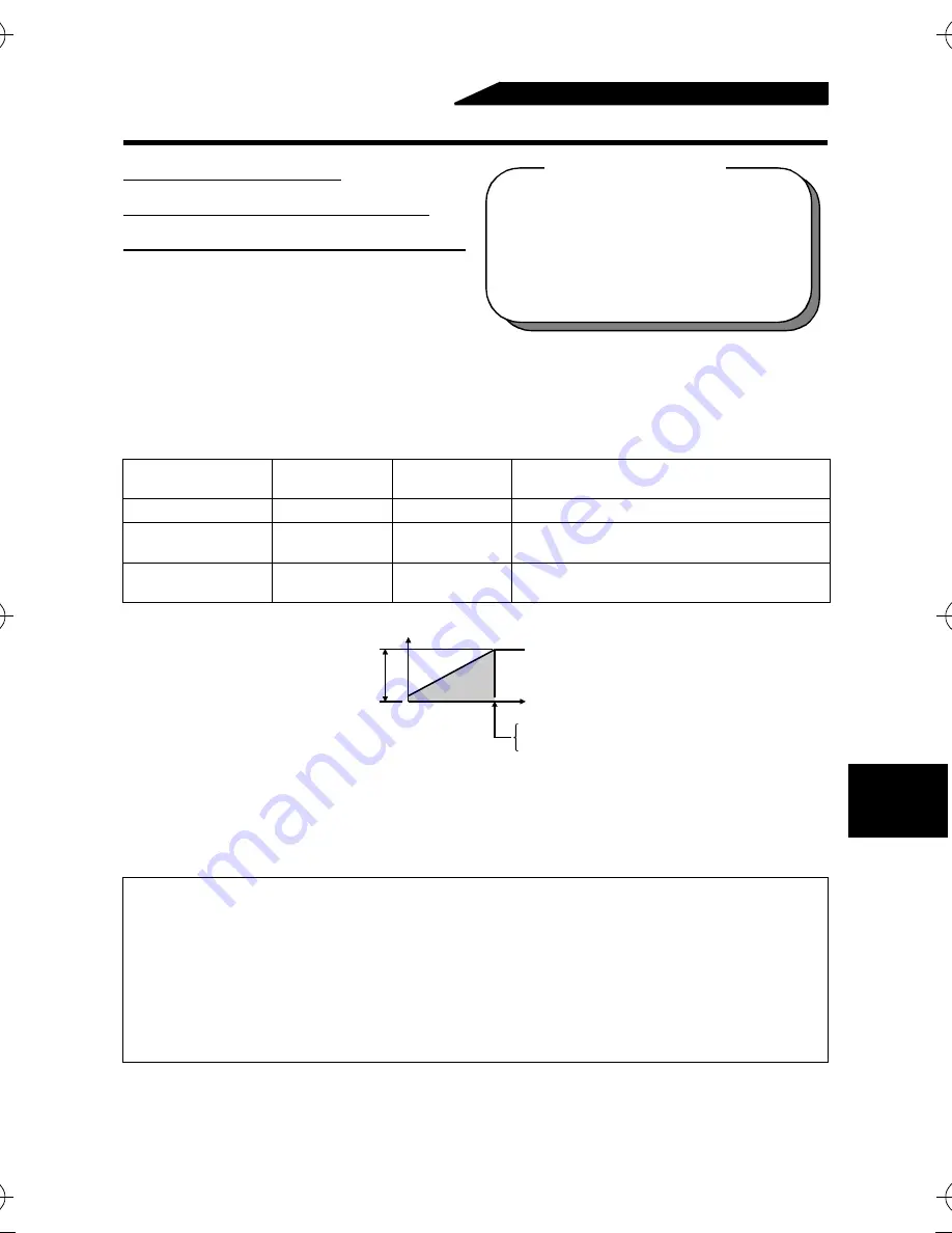
Pr.19
O
ut
put
v
olt
age
Pr.3
Pr.47
Output
frequency (Hz)
M4500E.book 73 ページ 2005年2月22日 火曜日 午後5時7分
Summary of Contents for M4000E series
Page 11: ...MEMO ...
Page 23: ...12 MEMO ...
Page 55: ...44 MEMO ...
Page 173: ...162 MEMO ...
Page 199: ...188 MEMO ...


