GB
FS 345 Door Controls / Rev.A 0.0 – 29
9.9 Emergency closing with 400 V DC opera-
tor
It is possible for the door to be closed using the door operator
when the fire alarm is activated.
Prerequisites:
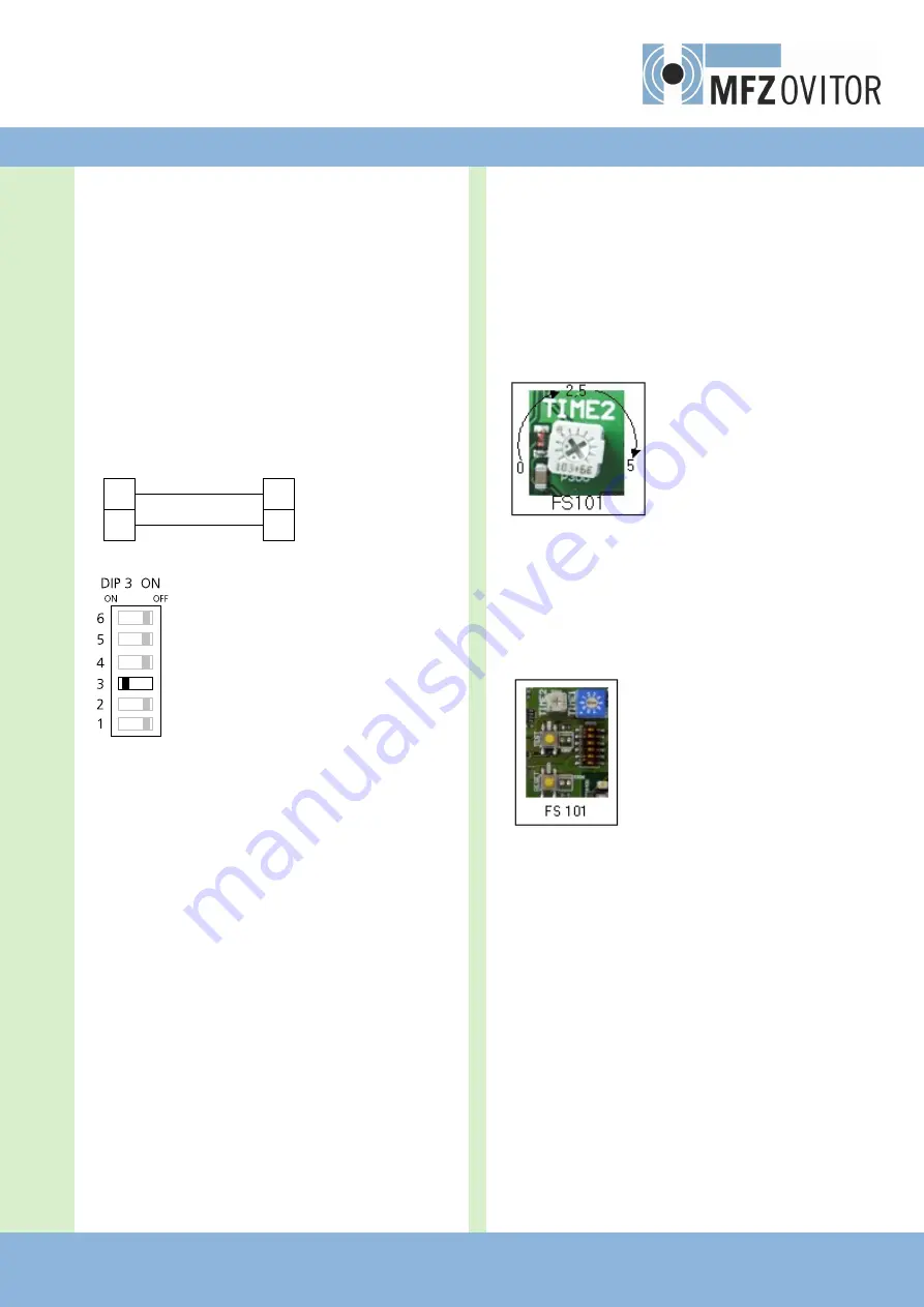
− Connect CS 300 X3/9+10 to FS 101 X04/5+6.
− FS 101 DIP switch 3 is ON (switch off mains voltage and
battery power)
Connect CS 300 FS circuit board +
9
10
5
6
X3
X04
CS 300 FS
FS101
In this case, if a signal is given by the fire alarm and mains
power is available, the FS 101 circuit board gives a DOWN im
-
pulse
X3 to the CS 300 FS circuit board via terminal X06.
The door is driven to the CLOSED end position in impulse
mode. The safety devices integrated are active. Once the
CLOSED end position has been reached, the door cannot be
opened again.
If the CESD (SKS) is activated during the closing phase, the
door reverses and stops at the OPEN end position. After 30
seconds a further DOWN impulse is sent. If the CESD (SKS)
interrupts the closing phase again, the process is repeated
3 times in total. If the CLOSED end position has not been
reached after 90 seconds, the door is then closed via emer
-
gency operation mode.
9.10
Door sealing function for FT fire door
operators
To ensure that the sections of the door close together tightly
in emergency mode, the door must be driven beyond the
CLOSE limit switch.
With the FS 345 control, this function is time controlled and is
set using TIMER 2. A value of 0 to 5 seconds can be selected.
Prerequisites:
−
Door operator type FT (DIP 1 is set to ON)
−
The system has been set in operation and the limit switches
have been set.
Settings:
1.
OPEN and CLOSE limit switches are set for normal
door operation.
2.
Set timer 2 to the mid-range value of 2.5 seconds.
3.
Drive the door to the OPEN end position.
4.
Switch off the mains voltage supply and press the
TEST button.
5.
The door runs to the CLOSED end position in emer
gency operation mode.
6.
The door is then driven beyond the CLOSE limit switch
for 2.5 seconds. Only then is power supplied to the
motor brake again and the door is held in position.
7.
Repeat steps 2 to 6 entering different values for timer
2 until optimum results are achieved.
8.
The CLOSE safety limit switch must be set accordingly.


