


10
User Interface
GX 1030
can only display parameters and waveform information for one channel at a time.
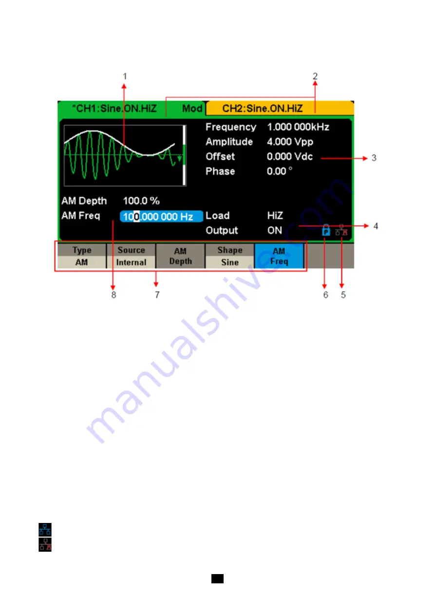
The picture below shows the interface when CH1 chooses AM modulation of a sine waveform. The information displayed may
vary depending on the function selected
Figure 4: User Interface
1. Waveform Display Area
Displays the currently selected waveform of each channel.
2. Channel Status Bar
Indicates the selected status and output configuration of the channels.
3. Basic Waveform Parameters Area
Shows the current waveform's parameters of each channel. Press Parameter and select the corresponding softkey to highlight
the parameter to configure. then use number keys or knob to change the parameter value.
4. Channel Parameters Area
Displays the load and output load, as selected by the user.
Load
---- Value of the output load, as selected by the user.
Press Utility → Output → Load, then use the softkeys, number keys or knob to change the parameter value; or continue pressing
the corresponding output key for two second to switch between High Impedance and 50 Ω.
High Impedance: display HiZ
Load:
display impedance value (the default is 50 Ω and the range is 50 Ω. to 100 kΩ).
Note:
This setting does not actually change the instrument's output impedance of 50 Ω but rather is used to maintain amplitude
accuracy into different load values.
Output:
Channel output state.
After pressing corresponding channel output control port, the current channel can be turned on/off.
5. LAN Status icon
GX 1030
will show different prompt messages based on the current network status.
This mark indicates LAN connection is successful.
This mark indicates there is no LAN connection or LAN connection is unsuccessful.