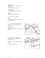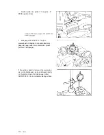
Gauge (01)
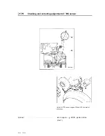
preignition chamber bore and set
dial gauge (07) on gauge to 5 mm pretension
(item 2).
Note
If cylinder head is removed, position gauge pin
of dial gauge directly on piston crown (177).
Use dial gauge holder 363 589 02 21 00.
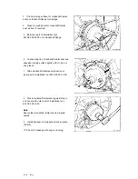
Engine
turn in running direction until dial gauge pointer
stops moving (TDC position), set dial gauge
scale to zero (item 3).
Engine
turn until dial gauge moves back 3.22 mm
on engines 602 and 603 or until dial gauge
moves back 3.65 mm on engines 601.921,
603.97 (item 4).
Note
Corresponds to crankshaft position of
ATDC.
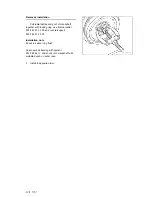
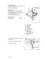
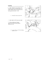
Holder for TDC sensor (42) or (44)
install locating device 603 589 01 21 00
(item 5).
Note
The pin on the crankshaft pulley or on the
vibration damper must catch in the groove on
the locating device, if not, correct position of
holder.
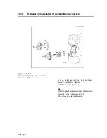
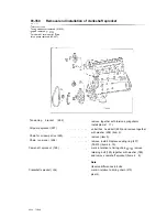
Holder for TDC sensor (42) or (44)
correct by loosening bolt
move holder for
TDC sensor until pin on crankshaft pulley or
vibration damper catches in locating device
603 589 01 21 00 and tighten bolt (41)
(items 6 8).
03.10
Summary of Contents for 602
Page 1: ...Mercedes Benz Mercedes Benz of North America Inc Montvale NJ 07645 ...
Page 5: ...General technical data 00 ...
Page 15: ...Crankcase and Cylinder Head 01 ...
Page 22: ......
Page 33: ......
Page 89: ......
Page 140: ......
Page 191: ...This page int ntiowally left blank 03 10 32113 ...
Page 227: ...ine Timing Valvstr ...
Page 282: ...Special tool f 05 10 310 5 ...
Page 301: ...ystern Air r Turbocharger 09 ...


