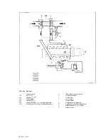
The exhaust gases of the engine are passed
through the exhaust manifold into the turbine
housing (h) and flow onto the turbine wheel (i).
The flow energy of the exhaust gases starts the
turbine wheel (i) rotating. This causes the
compressor wheel (d) which is connected
through the shaft (n) to the turbine wheel (i) to
be driven at the same speed. The maximum
rotation speed is approx. 135,000 rpm. The
fresh air drawn in by the compressor wheel (d)
is compressed and sent to the engine.
C
k
h i
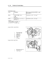
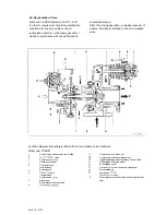
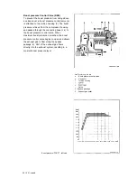
Functional diagram turbocharger KKK K24 (Engine 603.96)
a
Boost pressure control valve
C
Compressor housing
d
Compressor wheel
e
Control
f
bearing
g
h
Turbine wheel
k
Diaphragm
I
Valve
m
Charge housing
Shaft
Fresh arr
Compressed
(to engine)
Bypass passage/boost pressure control valve
Exhaust
Exhaust outlet
Oil feed
discharge
Control pressure
09.10 III
Summary of Contents for 602
Page 1: ...Mercedes Benz Mercedes Benz of North America Inc Montvale NJ 07645 ...
Page 5: ...General technical data 00 ...
Page 15: ...Crankcase and Cylinder Head 01 ...
Page 22: ......
Page 33: ......
Page 89: ......
Page 140: ......
Page 191: ...This page int ntiowally left blank 03 10 32113 ...
Page 227: ...ine Timing Valvstr ...
Page 282: ...Special tool f 05 10 310 5 ...
Page 301: ...ystern Air r Turbocharger 09 ...


